In case you did not follow this thread in the arduino forum, here is a summary.
We were able to adapt the ht1632 library written by westfw for the 2416 monochrome display, to the new and improved, bigger and better, 3216 dual color LED display (datasheet here).
The biggest challenge was to figure out that each chip (of the four) on the display board requires its own CS (chip select) signal. The result of this understanding allowed the modification of the old functions by adding an extra parameter to specify which chip will get the command or the data.
Below is a short video of the game of life running on Arduino 328 connected to the 3216 display. Note that an extra wire is required (to carry the CS signal), compared to the old 2416 display (which had 4 switches to select the CS "address", useful for cascading).
The demo code is available for download here (tested with Arduino IDE 21).
Monday, December 20, 2010
Saturday, December 18, 2010
New and improved "Dual LED matrix shield"
Updated June 12/2011
Added schematic and board images, and provided the Eagle files.
The latest revision of the "Dual LED matrix shield" is shown in the photos below.

This board is a bit longer so that it can be fitted with standoffs on both sides.
It also features an on-board tilt switch (white cylinder in the photo above), two push buttons and an infrared receiver.

The two RG (Red, Green, Yellow) LED matrices are inserted in the machined headers (round pins), after the components are soldered to the board.
The schematic and board (also available as Eagle files here and here, respectively) are shown in the images below.

(Click on the image to get a bigger size.)

Related posts:
Wednesday, December 8, 2010
Troubleshooting Wise Clock 2
It happened to me (and to others as well) that sometimes, after uploading the sketch, Wise Clock 2 displays the message "Failed to read quotes.txt from SD card" even though the SD card is inserted and has the right files on it. Obviously, this is a problem. First impulse is to try another SD card (and another and another). Still same error. Panic.
Here is a list of points to follow in this case.
Here is a list of points to follow in this case.
- check that all components are soldered (believe it or not, it happened to me once that I forgot to solder the 3V3 voltage regulator);
- check that all pins of the SD socket are soldered; since the kit comes with the SD card socket already soldered (by myself), any un-soldered pins is my fault (I apologize in advance if that happens; it did happen);
- with the multimeter, check all connections to the SD socket;
- make sure that the resistors in the voltage divider (4K7 and 10K, under the microcontroller) are correctly placed, as shown in photo 4 in the posting "Assembling Duino644".
Here is a tip on how to find out easily the polarity of a LED (especially useful for SMDs, either in circuit or not): with the multimeter's switch on the "check continuity" position (beeps), measure the "continuity" of the LED. The correct polarity will make the LED light up faintly.
Tuesday, December 7, 2010
Plastic case for BookClock
In case you did not like the bamboo BookClock (introduced here), this is another shot: a sleek, black plastic, version. The construction is similar to the wooden box, made of interlocking laser-cut plastic faces, with a transparent acrylic screen.


Related postings:
Saturday, December 4, 2010
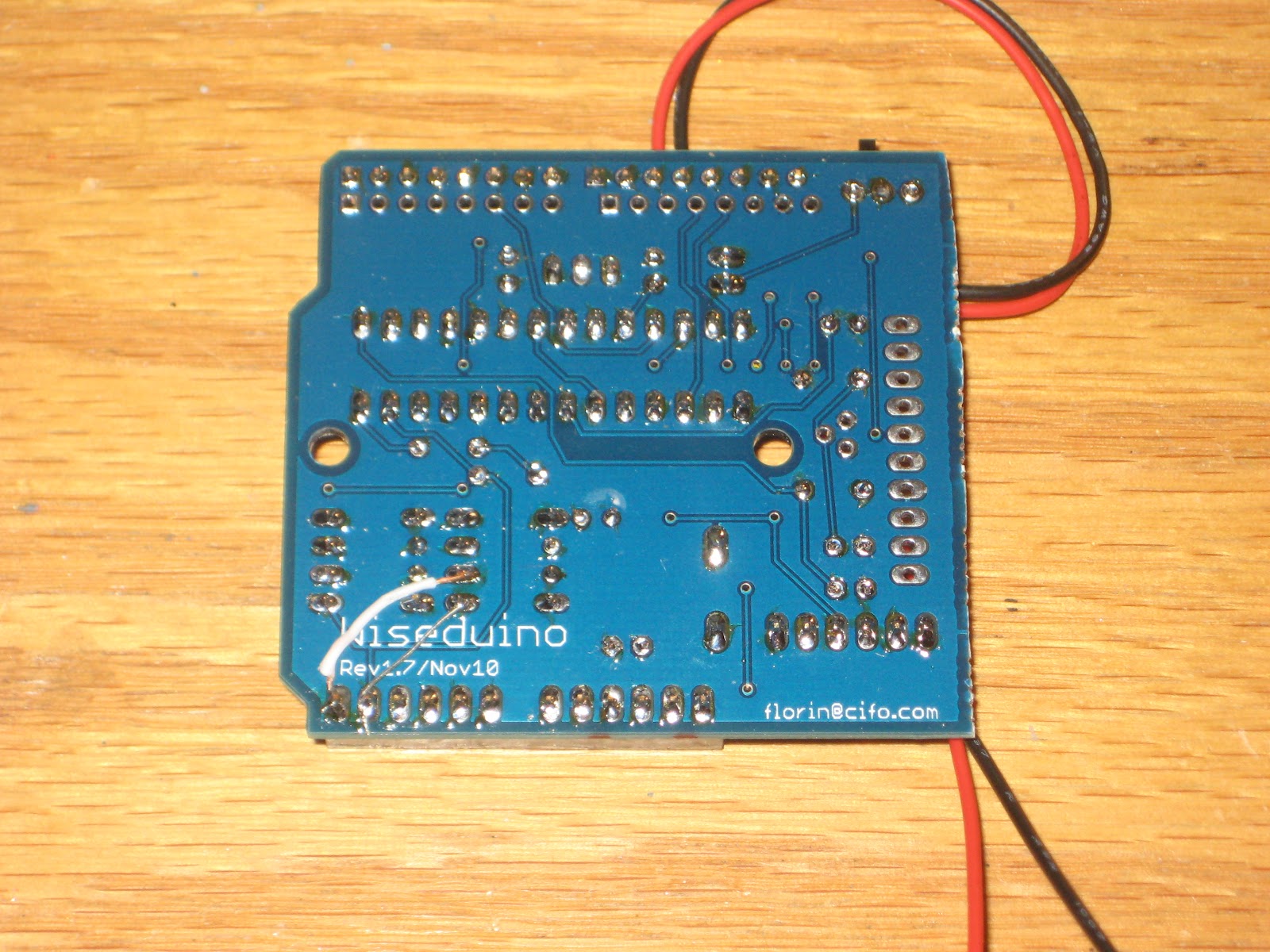
Wiseduino revision 1.7
Updated May 16, 2011
Courtesy of Scott, for those who want to take a quick peek (without downloading the Eagle files), here are the schematic in PDF and the board in PDF.
Updated Dec 14/2010
Revision 1.7 has a glitch: SCL and SDA pins of DS1307 are left un-connected. This should be an easy fix (shown in the photo below), yet an embarassing mistake on my side.

So here is the deal: until the whole lot is gone, every buyer of Wiseduino kit will get an extra one of these boards for free, or any other freebee by request.
Wiseduino is one of many Arduino clones, fully compatible with Arduino shields and Arduino software environment (IDE).
What makes Wiseduino unique is the on-board real time clock (with DS1307)(*) with backup battery, and the 32KB EEPROM (with 24LC256).
(*) Wiseduino+ has on-board DS3231, an extremely accurate real time clock.
The latest revision of Wiseduino is blue (as I mentioned in a previous post, black boards are not a choice these days anymore). In addition, these are the other differences:

I personally used Wiseduino for the WiseClock and BookClock projects. Others have used it for data logging (recording data to the external 32KB EEPROM) and general Arduino projects (since it is shield and software compatible).
The (corrected) board layout looks as in the image below.

The Eagle files can be found here (download schematic, download board).
Related posts:
Courtesy of Scott, for those who want to take a quick peek (without downloading the Eagle files), here are the schematic in PDF and the board in PDF.
Updated Dec 14/2010
Revision 1.7 has a glitch: SCL and SDA pins of DS1307 are left un-connected. This should be an easy fix (shown in the photo below), yet an embarassing mistake on my side.
So here is the deal: until the whole lot is gone, every buyer of Wiseduino kit will get an extra one of these boards for free, or any other freebee by request.
Wiseduino is one of many Arduino clones, fully compatible with Arduino shields and Arduino software environment (IDE).
What makes Wiseduino unique is the on-board real time clock (with DS1307)(*) with backup battery, and the 32KB EEPROM (with 24LC256).
(*) Wiseduino+ has on-board DS3231, an extremely accurate real time clock.
The latest revision of Wiseduino is blue (as I mentioned in a previous post, black boards are not a choice these days anymore). In addition, these are the other differences:
- changed layout: some of the parts are a bit re-organized;
- oscillator can also take a crystal (not only a resonator as before);
- manual trace routing: allowed for better connections (no traces between the header pins, for example).
All the other great features :) are still in place:
- on-board DS1307 (real time clock) with backup battery, and 24LS256 (EEPROM);
- support for XBee adapter from Adafruit (radio communication, remote uploading of sketches);
- parallel row of headers, compatible with prototyping boards;
- power micro switch;
- detachable prototyping area, with pad for an 8-pin SOIC;
- all ICs on sockets;
- 6-pin FTDI connector for uploading sketches (requires FTDI cable of FTDI breakout).
The new board is shown in the photo below.

I personally used Wiseduino for the WiseClock and BookClock projects. Others have used it for data logging (recording data to the external 32KB EEPROM) and general Arduino projects (since it is shield and software compatible).
The (corrected) board layout looks as in the image below.

The Eagle files can be found here (download schematic, download board).
Related posts:
Subscribe to:
Posts (Atom)


