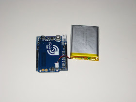
Duino644 was designed to match with (plug into) the now-discontinued 2416 mono-color LED display from Sure Electronics.
Wise Clock 3 board was designed to plug into the 3216 bi-color LED display from Sure.
Both boards have a similar schematic, based on ATmega644, and they share similar features: RTC (DS3231) on I2C, SD card, piezo buzzer, 3 user buttons.
There are a few differences between the 2 boards:
- Duino644 has IR receiver, connected on D2, whereas Wise Clock 3 has the Plus button on D2 and no IR receiver;
- Wise Clock 3 has D11 connected to pin 2 (CLK) of the 3216 display; on Duino644, since the 2416 display does not require an input on pin 2, D11 is not connected.
Our goal is to adapt the "old" Duino644 board to the 3216 bi-color LED display and run the Wise Clock 3 software on it. This is easily achieved by doing the following hardware hacks:
1. connect the processor's pin 17 to pin 2 of the display's connector (red wire in the photo);
2. solder a bridge between processor's pins 3 and 4 (also visible in the photo);
3. cut out the IR receiver.
Now upload the Wise Clock 3 sketch (download latest version from here).
Plug the Duino644 board into the 5mm display, as shown in the photo above, then power it with the USB miniB cable. Surprisingly, the ensemble looks pretty functional and practical as it is: the buttons are accessible at the top (albeit a bit deep), the board is flush with the display, and the power (USB) socket is on the right side.
The enclosure could be a similar pair of plexiglass plates as used in Wise Clock 3. This bigger Wise Clock 3 would be more suitable to be hang on a wall (rather than sit on a desk).
Note that the Duino644 I tested uses DS3231. A version with DS1307 should work the same (except it will show 0 as the current temperature, I think).
As always, feedback is appreciated.


