Saturday, January 28, 2012

Scrolling message sign display with Wise Clock 3/4 - part 2

This post, written some time ago, demonstrated how to make a message sign using two 3216 displays connected to Wise Clock 3. The font used in the demo is 8*8 (actually just 7*7), quite small for the 16 LED height of the display.

The code for a larger (11x14) font is already included in the Wise Clock 3/4 software (file fontLarge.h), just not used and used when the "Big Font" menu option is selected (file AppBig.cpp). I resurrected this forgotten font and the functions that use it and this is how it works:


I modified the original sketch (posted in this thread of the Arduino forum) to include the following lines at the top of the file:

char* msgLine = "           Hello world - demo for large font scrolling on dual 3216 display.";
int crtPos = 0;
int crtColor = GREEN;

and the loop() function:

void loop ()
{
  displayLargeScrollingLine();

  if (crtPos >= strlen(msgLine))
      crtPos = 0;
}

The source code for the demo in the video can be found here.


Related posts:

Friday, January 20, 2012

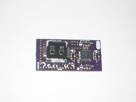
I2SDv3 - Arduino buckler with microSD

The Wyolum machine (these are the people who generously offered $3000 in innovation grants, with no strings attached) is forging ahead with a new and improved version of I2SD.
I just received their v3 prototype and it looks impressive. I must say it is the most feature-rich data logger / SD card backpack (here is the list of the competing products that I compared with).

Like its predecessor, I2SD v3 is a software-compatible Arduino (ATmega328/16MHz) with extras. It has on-board microSD card, DS3231 extremely accurate real-time-clock with backup battery, infrared receiver and 2 LED indicators for errors or status.


I2SDv3 comes assembled (all SMD), with the bootloader burnt in. Sketches can be uploaded through the FTDI connector.

The board can be plugged directly into Arduino, using one row of headers (A0-A4-GND-RST), hence the name "buckler" (like a "semi-shield", got it?)
I2SDv3 also offers header access to D4-D7 (v2 lacked that; my complaint was heard :), and it is compatible with the ChronoDot headers.

To test it, I decided to try the OpenLog library, by Nathan Seidle of Sparkfun. Surprisingly, it worked without a glitch from the first try. Well, kind of, I had to read the documentation :), and to change HardwareSerial.cpp, a "system file" (function SIGNAL(USART_RX_vect) is redefined in OpenLog.pde).

To emulate the OpenLog board closer, I changed the code to use D2 for the status LED, as shown:

from
#define STAT1  5 //On PORTD
int statled1 = 5;  //This is the normal status LED

to
#define STAT1  2 //On PORTD
int statled1 = 2;  // status LED on I2SDv3;

Note: The second LED of OpenLog board is connected to SCK (D13), so it blinks when the SD card is active (while reading or writing). The second LED on I2SDv3, being on D3, cannot be easily re-purposed.

Following OpenLog documentation, I connected to I2SDv3 using CoolTerm, typed in some text, pressed CtrlZ three times and voila!: file LOG0001.TXT got created and it contained the characters I typed in. Cool indeed.

Note: OpenLog won't compile with Arduino 1.0 IDE without some minor changes, as follows:
1. "WProgram.h" replaced everywhere with "Arduino.h"
2. function SdFile::write(uint8_t) must return size_t now (since it is virtual function defined in Stream.h); both SdFile.cpp and SdFat.h will need to be updated to reflect that.

Reminder: The OpenLog library should work with FAT32-formatted SD cards as well as FAT16. I will test it as soon as I get a 4GB microSD card.

Wednesday, January 18, 2012

MixiClock - 4 digits displayed on 8x8 LED matrix

So far, on a 8x8 LED matrix, I have only seen the time displayed with scrolling numbers (beside the geeky binary/hex/tix/dice/dots/bars or other coded formats). There is simply not enough room to statically display 4 digits at once, since the tiniest set of human-readable digits can be defined in a grid not smaller than 3x5 pixels.

I challenged myself to find an intuitive way to display 4 digits on the "standard" 8x8 matrix. I figured that this is possible if using 2 colors. Even though they may overlap a bit (quite literally), digits of different colors can be easily distinguished. This is because the overlap makes a third color: in the case of the bi-color (red/green) LED matrix, it will be orange.

I focused on two aspects:
  • font definition (3x5) as simple as possible, with minimal number of "on" pixels, but still readable;
// tiny 3x5 digits;
byte digit[10][5] = {
  {2, 5, 5, 5, 2},  // 0
  {1, 1, 1, 1, 1},  // 1
  {6, 1, 2, 4, 7},  // 2
  {7, 1, 2, 1, 6},  // 3
  {4, 5, 7, 1, 1},  // 4
  {7, 4, 7, 1, 6},  // 5
  {3, 4, 7, 5, 2},  // 6
  {7, 1, 2, 4, 4},  // 7
  {7, 5, 2, 5, 7},  // 8
  {2, 5, 7, 1, 6},  // 9
};
  • optimal placement of the digits on the 8x8 matrix, so the overlap is minimal (sometimes 1 pixel, very rarely 2 pixels). The photo below shows the starting point. There is more tweaking of the positions in the code, depending on the combination of digits.


As for the name, there are not too many choices, most of them are already taken, so I hastily settled for "MixiClock" (I am open to suggestions though :).

The sketch, written for my 8x8 bi-color LED matrix shield (also used in the original glass-domed Wise Clock) can be downloaded from here. It should be easy to adapt it to any other RG 8x8 LED matrix. The code also features setting up the clock using two buttons.


As you may have guessed, the top digits (green) indicate the hours, the bottom ones (red) the minutes. The position of the digits changes slightly depending on the combinations, so that there is no overlap or it is minimal (max 2 pixels, and those will be orange). The code is not final and I am sure it can be improved.

As always, comments and suggestions are welcome.

Sunday, January 15, 2012

Adventures in WiFly land - Part 1

This was a bit of a struggle, working with the XBee-footprinted WiFly RN-XV module from Roving Networks.

The goal was to get some data from the RSS feeds, kind of what this project had achieved.

First, I tried to set up the RN-XV module following this crash course (and using ladyada's XBee adapter with the FTDI cable). Everything went fine except connecting to my home WiFi network: I kept getting "AUTH-ERR". Eventually, after many tries, the module joined the network. I thought this is caused by the weak WiFi signal and other people may experience a similar scenario (which should be dealt with by the software).
Then I found with this software library, which, of course, did not work in my special case. After I started tweaking it and read the RN-XV manual once again, I found the explanation: WPA (which I am currently using) handshaking takes more than 1,000ms (1 second), which is the default timeout for the module. The solution was to increase this timeout (to 5000ms) with the command

set opt jointmr 5000

I ended up writing this sketch that makes requests to Yahoo's weather and stock quotes RSS feeds. It should work with the mentioned WiFly library (if they don't keep changing it).
Actually, I had to modify the library a bit too, to include my own specific commands in the initialization procedure. So I created this new function

boolean WiFlyDevice::myInit()
{
  if (!enterCommandMode())
  {
    DEBUG_LOG (1, "Failed to enter command mode");
    return false;
  }

  // turn off remote string;
  sendCommand("set com remote 0", false, "AOK");

  return sendCommand("set opt jointmr 5000", false, "AOK");
}

then modified begin() to look like this:

void WiFlyDevice::begin() 
{
  DEBUG_LOG(1, "Entered WiFlyDevice::begin()");

  if (!bDifferentUart) SPIuart.begin();
  myInit();
}

Another detail worth mentioning is the tuning of the delay between sending the request and reading the response. If this delay is too long, the response buffer gets overwritten, so response data is lost. If the delay is too short, the response is not there yet. Similar consideration while retrieving the response data from the buffer: we need to wait a bit for more data to come before we can say (kind-of) for sure that all data was received.

Next step (Part 2) is to parse the responses to find the correct values we are looking for, temperature and stock price, respectively, then to display them on Wise Clock 4.

Note: The RSS feeds I used are 
and
They could be custom-replaced with any other URL that returns a small(ish) set of XML data for easy parsing.

Wednesday, January 11, 2012

ZeeClock - nice mod running on Wise Clock 4

Here we have the first "independent" mod running on Wise Clock 4, thanks to Mr. Jon S!


Jon shared the code (download it from here) and added this description:

This is an alarm clock for my toddler who can't tell time (of course). It uses colors to tell him when he should be sleeping and when he should get up.
I didn't need to, but I wrote all the code so it's self contained including setting multiple alarms, setting the time, and turning the audio on and off.
It's not perfect (I'm an artist not a programmer so the code is a bit of a mess), but it does the job.

I think it's a great job!
Thanks again Jon.

Tuesday, January 3, 2012

Wise Clock 4 - time synchronization with GPS

This is my first foray into the world of GPS, made possible by the GPS XBee kit.
With Wise Clock 4 offering support for XBee, this little GPS module from seeedstudio seemed like a nice fit. The purpose is, of course, to synchronize the clock with the accurate time received from satellites.

Note: Some time ago I tried the WWVB atomic clock radio receiver module CMMR-6. It comes with a 60mm ferrite rod, pretty inadequate for receiving the Colorado radio signal in Toronto, more than 2200km away. On top of the fact that it is finicky (never worked for me), it is also bulky (the ferrite rod) and fragile (the thin antenna wire).

First, I inserted the module into the XBee adapter from adafruit, which is connected (through the FTDI cable) to a terminal session (9600, 8, N, 1).


Messages started flowing in, right off the bat: wow!


Next, I moved the GPS module onto the Wise Clock 4 and uploaded a sketch that uses TinyGPS library (modified by Justin).


Here is the serial monitor output.


For those who require maximum accuracy on top of the one provided by the DS3231 RTC chip itself, this GPS solution should do it.

Homework
Make the "Doomsday clock", like the one by Wyolum team shown in the video below, with Wise Clock 4 and 2 displays.


Update: Homework done.

Sunday, January 1, 2012

Old projects revisited

I recently had to revisit the (original, glass domed) WiseClock and the SillyClock.

On WiseClock I streamlined the software (download from here) to only show the time and quotes. It also allows the time to be set from buttons as opposed to the Sony TV remote control (the Reset button on the 8x8 LED matrix shield was re-purposed/re-routed). As well, the character set is now defined in progmem as opposed to internal microcontroller EEPROM (font1.h contains the font definition).
The method I chose for setting the time is to show the hours in red and the minutes in green, and alternate between hours and minutes by pressing the left button (now named "Set"). The left button (the former "Reset") is now named "Inc" and connected to A2/D16 (a pull-up 10k resistor is also required), as shown in the photo.


This button is used for incrementing the hours or minutes. Once the right time is set, the clock will revert to displaying the scrolling quotes and time.

On SillyClock, the software (download from here) can now handle the tilt switch (on the "Dual RG bi-color LED matrix shield") and also sound the alarm.
Two hardware hacks are required:
  • addition of a pull-up 10k resistor on A0;
  • addition of a piezo buzzer between A1 and ground.