Updated Sep 29, 2011
Check out the newest LED matrix shield here.
Updated Sep 1, 2011
As of today, this kit is no longer offered, since I ran out of LED matrices. If you are still interested in the PCBs (because you already have a compatible LED matrix, for example, or maybe you just want to adapt a similar one), drop me a line.
Updated Feb 16/2010
The 40-pin female header, meant as a socket for the LED matrix, was replaced with two 12-pin machined female headers (see this posting), a much better solution. In the same time, since these headers are shorter, the LED matrix will be closer to the board, touching on the ICs underneath. Therefore, I eliminated the 3 IC sockets, since they do not make sense anymore.
Also, the 220 ohms resistor was replaced with a 110 ohms.
Paired with Wiseduino, which has on board RTC (real time clock) DS1307 and EEPROM 24LC256, it makes the Wise Clock.
(Please check out The Shoppe for more kits.)
The LED matrix shield kit includes the following components:

Schematic can be downloaded here (Eagle file).

Board layout (download Eagle file here)

Assembling instructions are here.
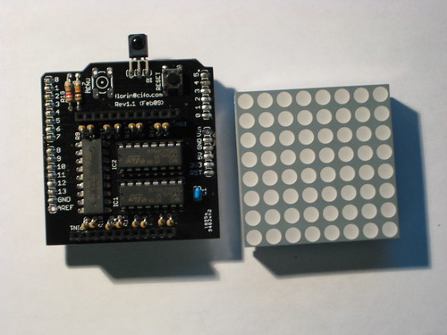
- PCB, black;
- 8x8 bi-color (red + green) LED matrix, medium size (47 x 47 mm);
- 2 x 74HC595 shift registers
with 2 x 16 pin sockets; - ULN2803A
with 18 pin socket; - 17 x 110 ohm resistor;
- 2 x micro push button;
220 ohm resistor;- 10K resistor;
- 2 x 100nF capacitor;
40 pin female header; 2 x 12-pin machined round female header;- 40 pin male header;
- infrared receiver.

Schematic can be downloaded here (Eagle file).

Board layout (download Eagle file here)

Assembling instructions are here.
See related posts:


Those type of female headers are pretty crappy for the thin leads of the matrices. The small pins tend to get dislodged from between the prongs of the fork shaped piece of metal inside the header.
ReplyDeleteI don't know what connectors you have used, but those in the kit are (the only) perfect fit for the LED matrices. I built quite a few shields with great results, trust me.
ReplyDeleteWhy 595's are used directly without any transistors? They can't source enough current for the full row.
ReplyDelete595's max output current is 25mA, enough to drive a LED, which takes 20mA or less.
ReplyDeleteI have one on my desk working continuously for about a year now, and the chips are not even warm.
As I understand, ULN2803 sinks the current from full column whereas 595's drive the rows. When the whole row is lit up, doesn't 595 need to source 8×20mA = 160mA, which exceeds its maximum *total* output current?
ReplyDeleteAn output from 595 drives just one LED at any given moment. The 595 output sources a whole column indeed, but ULN2803 sinks the rows one by one, through the software. So, at any given moment, one output of 595 will only source one LED.
ReplyDeleteYou're absolutely right, but I'm talking about total 595 current, through all its pins combined. Datasheet on TI's 595 specifies 70 mA to be maximum «continuous current through VCC or GND» of 595, so in case all outputs of 595 are sourcing 20 mA this total limit may be exceeded.
ReplyDeletePerhaps it's not a huge problem since in most applications only a fraction of all matrix LEDs are lit so 595's don't have to source through every pin all the time.
Nice shield anyways, kudos for sharing schematics.