My first blog posting is about this clock I made, I called it
Wise Clock.
What does it do?
Mainly, it displays the time on an 8x8 LED matrix display.
Why is it wise?
Besides the time, it can also display quotations, intense snippets of text invented by some smart people.
What else can it do?
What can one display on a screen with the resolution of 8x8 pixels? Not much: Conway's game of life, audio spectrum analyzer, maybe some animation with moving sprites, a la Space Invaders.
How practical is it?
It can be powered by batteries, which can last a few days.
It can take commands from a TV remote control (infrared).
It can be turned on and off by the remote control as well, much as a TV can.
There are plenty of quotations, about 32K worth, so one does not get bored reading the same stuff over and over. Not that there is anything wrong with that (since the repetition is the mother of learning, and throwing quotations in one's discourses is guaranteed to show how smart one is).
What's inside?
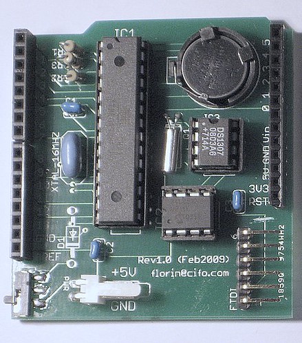
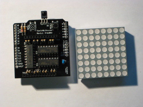
I started from an Arduino board with atmega 168. I added a shield with the RTC (DS1307) and EEPROM (24LC256). I added a second shield with the led matrix display, with 595 shift registers. Then I combined the Arduino and the RTC shield on one PCB, the size of a small shield. So I ended up with an Arduino "clone" ("clockuino"?), with the display shield on top.
I upgraded the processor to atmega 328. The character font is now stored in the internal EEPROM. The base board does not have the FTDI chip on it. Connection to the PC is done through the FTDI cable. Also, there is no voltage regulator, since the intention is to power it from 4 AA (rechargeable) batteries.
I posted the schematics
here.
This is how the base (microcontroler) board looks like:
and this is how the display shield looks like:
A video of the
Wise Clock in action can be seen
here.