Sunday, July 26, 2009

Buy Wiseduino kit

Update July 5, 2015
A redesigned wsduino is now available.

Updated Apr 24, 2012
This kit is now DISCONTINUED.

Updated Dec 5, 2010
I am currently shipping the latest revision of Wiseduino, which is 1.7.
Wiseduino+, a similar board but featuring DS3231 (extremely accurate real time clock) is also available, check it out here.


Updated Aug 1, 2010
I still have this kit for sale, with a newer, improved, board.

I have a few Wiseduino kits for sale, for US$34 each, free regular shipping in North America (add US$4 for any other destination in the world).

The Wiseduino kit includes the following components:
  • Wiseduino PCB;
  • ATmega328P programmed with the bootloader;
  • 28 pin socket for ATmega328P;
  • resonator 16MHz;
  • 24LC256 EEPROM, in either DIP or SOIC package (depending on the availability);
  • DS1307 real time clock, in either DIP or SOIC package (depending on the availability);
  • crystal 32,768 Hz;
  • coin battery holder;
  • 3V coin battery (CR1220 or compatible);
  • 4 x 10K resistor;
  • 4 x 100nF capacitor;
  • 40 pin female header;
  • 10 pin female header;
  • SPDT micro switch;
  • either molex 2-pin angled power connector or JST jack;
  • power cable, with battery connector at one end and female 2-pin plug at the other end;
  • 6 pin male angled header.
(Missing from the photo are the battery clip+ wire, the micro switch and the CR1220 battery.)

Assembling instructions can be found here.
Wise Clock sketches, formatted and commented, are published here (coming soon).

This is an Wiseduino assembled on a test PCB (green).
The release version is black.

Related posts:

The shoppe


Here are a few original kits you can buy from us. They are all open source, with schematics, board layout and software freely available.

Wise Clock 4 complete kit - US$125 US$115, free shipping to North America
Has support for wireless devices with an XBee footprint (XBee, Bluetooth, WiFi etc).
Includes everything needed to build the clock in the left photo except the SD card and USB cable (ask if you need those).


Wise Clock 4 kit - US$67 US$57, free shipping to North America

Includes the PCB and all parts to build the board in the left photo.


HDSP-2534 clock kit - US$40, free shipping to North America

Includes the PCB and all electronic components to build the clock in the photo. The phone dock/cradle is not included.


ProMini bubble clock shield - US$18, free shipping to North America

This kit includes mostly SMD parts to build the ProMini clock shield in the photo. Use your own ProMini.


ProMini OLED clock shield - US$30, free shipping to North America

This kit includes the parts, some SMD, some through-hole, to build the OLED clock shield shown in the left photo. Use your own ProMini.


WiFiChron alarm clock kit - US$47 w/o case /$61 with case

Make a desktop/nightstand alarm clock with WiFi capabilities.
Could be customized (through adapters) for other types of similar displays.


6-character alphanumeric Arduino shield kit - US$26 (free shipping to North America)

Quickly and easily add alphanumeric display capabilities to your Arduino projects.


wsduino - Arduino-compatible with on-board RTC and XBee support - US$27 (free shipping to North America)

Make a clock with no extra shields.


More stuff:

        The following have been discontinued and are no longer available. I may still have one or two laying around, so please ask if you really need any.
            • Wiseduino+ kit - Arduino-compatible featuring extremely accurate real time clock DS3231 - 

            Buy Wise Clock kit

            Updated May 14, 2011
            This kit is DISCONTINUED due to the availability (and affordability) of glass domes. You can still build this project if you provide your own 4" (height ) x 3" (width) glass dome (found on ebay). To complete the WiseClock, you will need the Wiseduino kit and the LED matrix shield kit.


            Wise Clock kit, ready to be assembled; requires soldering, of course.


             (US$79, free shipping in North America)

             (US$83, free shipping outside North America)


            The Wise Clock kit consists of:
            • the Wiseduino kit plus
            • the LED matrix shield kit plus
            • the glass dome case.
            Broken down to the components, this is what you get:
            • Wiseduino PCB;
            • ATmega328P programmed with the bootloader;
            • 28 pin socket for ATmega328P;
            • resonator 16MHz;
            • 24LC256 EEPROM, in either DIP or SOIC package (depending on the availability);
            • DS1307 real time clock, in either DIP or SOIC package (depending on the availability);
            • crystal 32,768 Hz;
            • coin battery holder;
            • 3V coin battery (CR1220 or compatible);
            • 4 x 10K resistor;
            • 4 x 100nF capacitor;
            • 40 pin female header;
            • 10 pin female header;
            • SPDT micro switch;
            • either molex 2-pin angled power connector or JST jack;
            • 6 pin male angled header;
            • Wise Clock LED matrix shield PCB;
            • 8x8 bi-color (red + green) LED matrix;
            • 2 x 74HC595 shift registers with 16 pin sockets ;
            • ULN2803A with 18 pin socket;
            • 16 x 100 ohm resistor;
            • 2 x micro push button;
            • resistor 220 ohm;
            • resistor 10K;
            • 2 x 100nF capacitor;
            • 40 pin female header;
            • 40 pin male header;
            • IR receiver;
            • battery holder for 4 AA rechargeable batteries;
            • battery connector + cable;
            • molex 2-pin female connector;
            • glass dome case.
            Assembling instructions for the Wiseduino kit can be found here and for the LED matrix shield kit here.
            Source code (sketch) can be downloaded here.

            Friday, July 24, 2009

            Brief comparison between SD card shields

            Before I started the Wise4Sure project, which uses SD card, I did some research on a few SD card shields available commercially. This post is a summary of my findings.

            I looked at three SD card shields: one from Libelium (US$28), one from Seeedstudio (US$15) and Wave shield from Adafruit (US$22, although this is more than an SD card shield).

            The similarities are:
            • all SD cards require 3.3V;
            • all connect to the SPI port (pins 10-13);
            • they all need a voltage divider (2 resistors x 3 signals) to adapt between the 5V level from Arduino and 3.3V level of the SD card;
            These are the particularities:
            • Libelium's small form factor shield comes assembled (SMD components) and tested, and includes a microSD card. It offers the nice feature of plugging the shield to either pins 8-13 (power is extracted from pin 8, set as high) or to the ICSP connector. It is not stackable (no more shields on top of it). It makes its own 3.3V from an onboard regulator.
            • Seeedstudio's also small form factor comes assembled and tested. It accepts both SD and microSD, manually selectable through a switch. 3.3V comes from Arduino. It is also not stackable.
            • Adafruit's Wave shield is a full size shield, designed to play wave files from the SD card. It comes as a kit, with through-hole components and clear assembling instructions. It has a powerful (100mA) 3.3V regulator on board and it is stackable. After interfacing with Wave shield, only pins 6 to 9 are left available for other use.
            In my pre-prototype of Wise4Sure I used the Wave shield, since it was the only SD card shield I had. The integration went seemlessly, everything worked from the start.

            Monday, July 20, 2009

            When 2K is not enough

            Good thing I started Wise4Sure as a "pre-prototype" (proof-of-concept). Imagine the frustration of things working weirdly with a prototype board, parts soldered maybe not perfectly, wires over wires, solder bridges and many other potential hardware issues. Then realize that the problems are really in the software, where 2KB of RAM is not enough, due to the SD card library (SHuFAT), which itself uses a half KB buffer to read a sector (see this post).

            Based on the newly acquired facts, I decided that the prototype will use an ATmega644, the core of the sanguino. Here are a few technical specs:
            • 4KB static RAM (that's the main reason I chose it);
            • 64KB flash memory;
            • 2KB EEPROM;
            • completely through-hole.
            Not many stores sell the sanguinos, nor the ATmega644, especially with the bootloader. I ordered mine from wulfden.org.

            I already started building the board, and one of the first observations is that the distance between the two connectors (2x8-pin) on the back of the 0832 display module from Sure is not multiple of 0.1", as I expected. So my plan to use the connectors as plug-ins the "mother-board" is half ruined. I may need to use only one connector, which would confer less mechanical sturdiness, or have the "mother-board" un-attached mechanically, but connected through the short parallel cable that comes with the display. Both suck.

            Related posts:

            Sunday, July 19, 2009

            Introducing Wiseduino

            Update Feb 15, 2016
            A new revision of this board, now renamed wsduino, is available here.

            Updated Dec 5, 2010
            Wiseduino has reached revision 1.7.


            Updated Oct 30, 2010
            Check out Wiseduino+ here.


            Updated Oct 4, 2010
            A newer and improved version of Wiseduino was introduced here. The main difference is a prototyping area, which can be cut off if desired (and used as a breakout board for a 8-pin SOIC surface mounted IC).


            Wiseduino is an Arduino-compatible microcontroller board, which includes a DS1307 real time clock (RTC) with backup battery, a 24LC256 EEPROM chip and a connector for XBee adapter for wireless communication.

            Wiseduino is completely compatible with the Arduino project software and IDE, and also pin compatible with the existing shields.

            Some of the features are:
            • PDIP ATmega328P on socket, running at 16MHz;
            • fully compatible with Arduino shields;
            • by design, the board accomodates either SMD or through-hole version of DS1307 and 24LC256, respectively;
            • small form factor, the size of the protoshield;
            • 6-pin FTDI connector with automatic reset capability;
            • standard 2-pin power connector (either MLX-WF02R from molex or JST jack from seeedstudio) for externaly regulated 5V;
            • power on/off micro switch, easily accessible on the side;
            • extra row of headers for digital pins, with 0.1" gap, for the use of prototype boards;
            • available interrupt output pin from RTC;
            • the onboard backup battery (CR1220) allows RTC to keep time even when Wiseduino is not powered;
            • minimal power consumption when processor is in sleep mode;
            • XBee adapter can be connected independently of shields, through its own separate connector (normally, the XBee device is required to be on top of the shield stack, to avoid RF "shielding");
            • remote sketch upload through XBee (see "how to" article).

            Schematic

            Circuit Board

            Download Eagle files:
            Shown in this photo is the Wiseduino test PCB (green). The release version will be black.

            This is an assembled (test) Wiseduino.

            Wiseduino is the base for Wise Clock, whose main function is to display scrolling time and quotations on a LED matrix display.

            You can order an Wiseduino kit here or visit The shoppe for more products.


            Creative Commons License
            Wiseduino by FlorinC is licensed under a Creative Commons Attribution-Share Alike 2.5 Generic License. Based on the work at www.arduino.cc.

            Wise4Sure - Wise Clock with LED display from Sure Electronics

            I was finally able to finish the "pre-prototype" of Wise4Sure, the version of Wise Clock that uses a 32x8 LED display from Sure Electronics. These LED matrices are single color (I have seen red, green and yellow so far), have a controller on board (Holtek1632) and can be bought for about US$10 (free shipping). Unbeatable. So, I could not resist the temptation of building Wise Clock around this display. Courtesy of Mr. Bill Westfield ("WestfW") who wrote the demo sketch (see here), displaying to the Sure LED matrix module becomes a trivial task. With a few small modifications (adaptations from the original 24x16 matrix to my 32x8), the sketch worked perfectly.

            Another "improvement" is the introduction of the SD card. Previous versions of Wise Clock stored the text quotations in EEPROM, which had a few inconveniences:
            - there was a limit of 32KB of storage;
            - the process of loading the EEPROM was relatively complex and time consuming.

            Replacing the EEPROM with an SD card solves these inconveniences and offers a few other advantages:
            - quotations (or any message for that matter) can be changed/updated much easier, since it involves only the modification of a text file;
            - quotations can be edited with a PC, directly on the SD card;
            - there is no need to transfer the text, from a file on PC to Arduino, through serial port.

            Integrating the SD card with Wise4Sure was the challenge. From h/w perspective, all SD solutions use the SPI (digital pins 10-13). As for the s/w, I opted for SDuFAT, from Arduino playground. It seems that this library is RAM hungry (I should mention that I did not look at the others, which may be as hungry). A big chunk of RAM, 512 bytes, is taken by the buffer that stores a sector after it is read from SD. (So, I assume that all other libraries should have this buffer as well).

            After I eliminated some variables and functions which I did not use, everything (scrolling quotations) seemed to be working fine. Until I included the code for RTC (DS1307), when the returned time was consistently same bogus value. I narrowed the problem down to, again, memory (RAM) use. I adjusted my own text buffer a million times, until I got the RTC working. You may ask, as I did, what has the RTC got to do with the memory? Well, I can tell you, when the RAM is in "short supply", the time returned from RTC is just wrong (for example, "18:00" at all times). Keep in mind that RAM is consummed by the processor/program stack as well: the more functions are called, and the more parameters are passed, the more RAM is taken.

            I said "pre-prototype" because, as SD card "shield", I used ladyada's Wave Shield. As for Arduino, I used my own Arduino clone, WiseDuino (just came up with the name, it used to be called Wise Clock, but this may lead to confusion). By the way, WiseDuino is now at revision 1.3 and the PCB is being manufactured by seeedstudio. I should be getting some boards soon and it seems that they will be also available for sale, under open source projects, from seeedstudio.com site.

            In the end I got it working, so here it is in action (video).

            The device is currently powered by 4 AA eneloop rechargeable batteries. The measured consumption is around 200 mA (as mentioned, using Wave Shield as SD card module). For practical purposes, this may require a wall wart power supply.

            Next step is to build a real prototype, on perfboard, attached to the LED display board. Basically a whole Arduino, with an RTC and an SD card, with connectors for the LED display (pseudo) "shield".

            Wednesday, July 8, 2009

            Form over substance (part 2) - Examples of enclosures

            Here is a collection of enclosures I assembled from the internets. These could provide some inspiration for future projects. The list is sorted by cost, ascendingly.
            Everyone can draw their own conclusion, I am not going to comment on pros and cons (and make this post even longer).


            Cardboard case

            Jar case - Fireflies

            Pelican case - XBox controller


            Plastic Ferrero-Rocher chocolate box - Wise Clock rev 0.1

            Cigar box

            Altoids mint box - MintyBoost

            Open side (open back) sandwich enclosure

            Glass dome - Wise Clock

            Moded book case - X10 Book

            Photo storage box - Wide Clock

            "Encased" by design - Let's piano

            Plastic electronic enclosures from Polycase

            Aluminum case from seeedstudio

            Sparkfun project case

            Plastic enclosures from Hammond

            Acrylic stand for LCD

            Custom made, laser-cut, acrylic faceplate - Monome

            Custom made wooden case - Life Clock

            Custom made wooden case + hard disk enclosure - Hifiduino

            Cubesat (very very cool, also very very expensive)


            Other ideas:
            - lego themed enclosure;
            - display case for 1/43 model cars;
            - iPhone (or similar small consumer electronics) cardboard case;
            - hangable (wall mount) floater frame, with mesh wires supporting the exposed electroncs;
            - reclaimed/repurposed/reused electronic devices (modem, hard disk, iomega drive, radio, amplifier);
            - modified clock (either desk or wall) case;
            - cassette/VCR tape case;
            - soap box (similar one is actually on sale at sparkfun);
            - slice (1-2") of a large diameter (>4") PVC tube, with acrylic transparent/translucent covers (many years ago I made a round clock case like that);


            See also:

            Monday, July 6, 2009

            Form over substance (part 1) - on project encasing

            This is an attempt to gather, discuss and summarize the choices for encasing a small, Arduino based, electronic project. I wrote this article after I read a discussion thread on encasing, in the Arduino forum. Although some good, rich sources have been mentioned, the general conclusion was that one still cannot pick a case and use it as is, without heavy modification (and even that was considered a success). This is because there are so many choices for electronic components out there, so many layouts for the boards, so many shapes for the LCDs etc. As much success was achieved with the "standard" Arduino (take the shields for example), there is still a lack of "standardization" in the field of enclosures.

            Personally, I find encasing as important as any other step of the development process, since the main purpose of the case/enclosure is to protect the electronics. To me, a project that is not encased is not finished (I have many un-finished projects myself).

            I hope this article will give readers some ideas. As always, any suggestions/recommandations are welcome.

            Factors to take into consideration when choosing/making an enclosure, not necesarrily in the order of importance:

            1. Ready-made vs. custom designed and made

            o Ready-made cases are of 2 types: generic (used for display, storage etc), and those specifically designed for electronic projects;

            § Among the amateur projects, many enclosures are re-purposed generic cases/boxes, where creativity and imagination in choosing the best one play a big role;

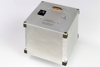
            § Electronic enclosures tend to be boxy, dull looking, un-inspiring, although strong, sturdy, solid.

            o Generic cases, usually, need some custom work (drilling, cutting, painting);

            o Custom made enclosures require, obviously, more skill and time;

            2. Portable vs. stationary

            o Portable/pocket cases need to store the power supply (batteries etc); may need additional electronics to accommodate portability (battery recharging, LCD display etc); should be light and sturdy, shock/vibration resistant, sometimes waterproofed;

            o Stationary enclosures could be heavier, bulkier; they could be designated for indoor or outdoor usage, leading to different sets of requirements;

            3. Price/cost/work/effort/tools

            o This factor is relevant for custom made enclosures, since it takes a greater amount of work (time, effort and tools) to build a custom made enclosure than to modify a ready made one;

            o Cost is dependent on the materials used (titanium sheets are more expensive than aluminum sheets, which are more expensive than PVC, for example); the rule is: the softer the material, the easier (and cheaper) to process;

            o Cost could be minimized if reclaimed/recycled materials are used;

            o Depending on the tools on hand, materials also determine the amount of work required, that is, some materials require specialized tools (bending/cutting/welding metals, for example);

            4. Aesthetics

            o Normally, given the amount of extra effort, a custom case should look more appealing than a ready made one;

            o Aesthetics involve shape, proportions, usability (buttons, lights, LCD), color(s)/paint, materials etc.

            5. Environment

            o Depending on the environment, the enclosure may be required to withstand dust conditions, humidity, heat, vibrations etc. Selecting the right material accommodates most of these cases.

            o Also, sealing and insulation may be considered.

            6. Heat dissipation/cooling

            o The electronics inside may dissipate heat through a radiator. In this case, the material for the enclosure should be metal.

            7. Robustness/durability

            o Robustness is more relevant for portable devices, where they may be dropped, squeezed, bent, scratched etc.

            o Ready-made enclosures, since they are usually made of injected plastics, may be more robust than the custom made ones.

            o Enclosure cover should be kept in place with screws, rather than with hinges and hook (or magnets).

            8. Material

            o Dependent on many of the above factors.

            o Material could be chosen for aesthetical considerations (glass is more elegant than acrylic, for example), ease of alteration (e.g. plastic vs. metal), environment (e.g. wood would not be suitable in humid conditions), robustness (e.g. plastic vs. cardboard);

            9. Ease of access to batteries/parts for upgrades/maintenance

            o This may be an important factor for battery-powered devices, since they would need battery change more frequently. Access to batteries should not require tools (screwdriver) and be possible, ideally, through a hinged or snap cover.

            o For the devices requiring periodical upgrades, a connector should be exposed out of the enclosure, so there would be no need to open it up.

            10. Attaching the electronics to the case

            o Depending on the “portable vs. stationary” factor, the PCB and other internal components (buttons, LEDs, LCD, battery holders) could be attached to the case with screws, padding, Velcro, ties, glue;

            11. "Cool" factor

            o Projects that are alike electronically (schematics) will be differentiated by the case/enclosure. Creativity has a decisive role in either choosing a “cool” ready-made case (and tailoring it) or making a custom one from scratch.

            o Some enclosures may follow a theme (lego, batman, star wars etc);

            o Enclosures may have particular shapes (e.g. robot, clock, guitar, monome), paint jobs, colors, materials.


            Related posts:

            Form over substance (part 2) - Examples of enclosures


            SMD & TH revisited

            Mr. kg4wsv pointed out a potential problem with the latest (revision 1.2) Wise Clock PCB: the SMD pads are "awfully closed" to the 2 DIP pads, so short circuits from accidental solder bridges may occur.
            Although the DRC check passed successfully, a closer look revealed that indeed, the pads are dangerously close.
            I fixed the problem by changing, in their respective libraries, the 2 pads of the DIP ICs, making them "round" instead of "long".
            This is how the latest PCB looks like:

            Saturday, July 4, 2009

            Wise Clock PCB goes SMD & TH

            Finally I succeeded in designing the Wise Clock PCB to accomodate both SMDs and through hole components. Well, not for all ICs, just two of them: DS1307 and 24LC256. Quite a challenge, since full overlapping is not possible (due to the different gauge between pins, although the widths are identical).

            To recap, Wise Clock is an Arduino clone, fully compatible with the existing Arduino shields. Wise Clock offers an RTC (DS1307) with a backup battery, and an EEPROM (24LC256), both connected on I2C pins (analog 4 and 5) of Arduino. Wise Clock is powered by a regulated 5V power supply (2 pin molex connector) and connects to the serial port through the FTDI connector (lower right corner in the image below).

            A new feature of the latest board (version 1.2) is the optional connection with an XBee adapter from adafruit. This is possible through the 10 pin female header at the bottom of the board. The XBee adapter also supplies the 3.3V to the Arduino "3V3" expansion pin. There is also circuitry on the board that allows to remotely reset of the microcontroller and to upload sketches (adapted from the adafruit XBee tutorial).

            Here is how the board looks like. The EEPROM and DS1307 are placed in the upper right corner (the SMDs cover pins 2 and 3 of the TH package).


            Now I could solder on the board either the SMD (cheaper) or the through hole. And since they somehow overlap, there is no chance to mistakenly solder both SMD and TH of the same component.

            Next steps are to order the board and actually build and test it.