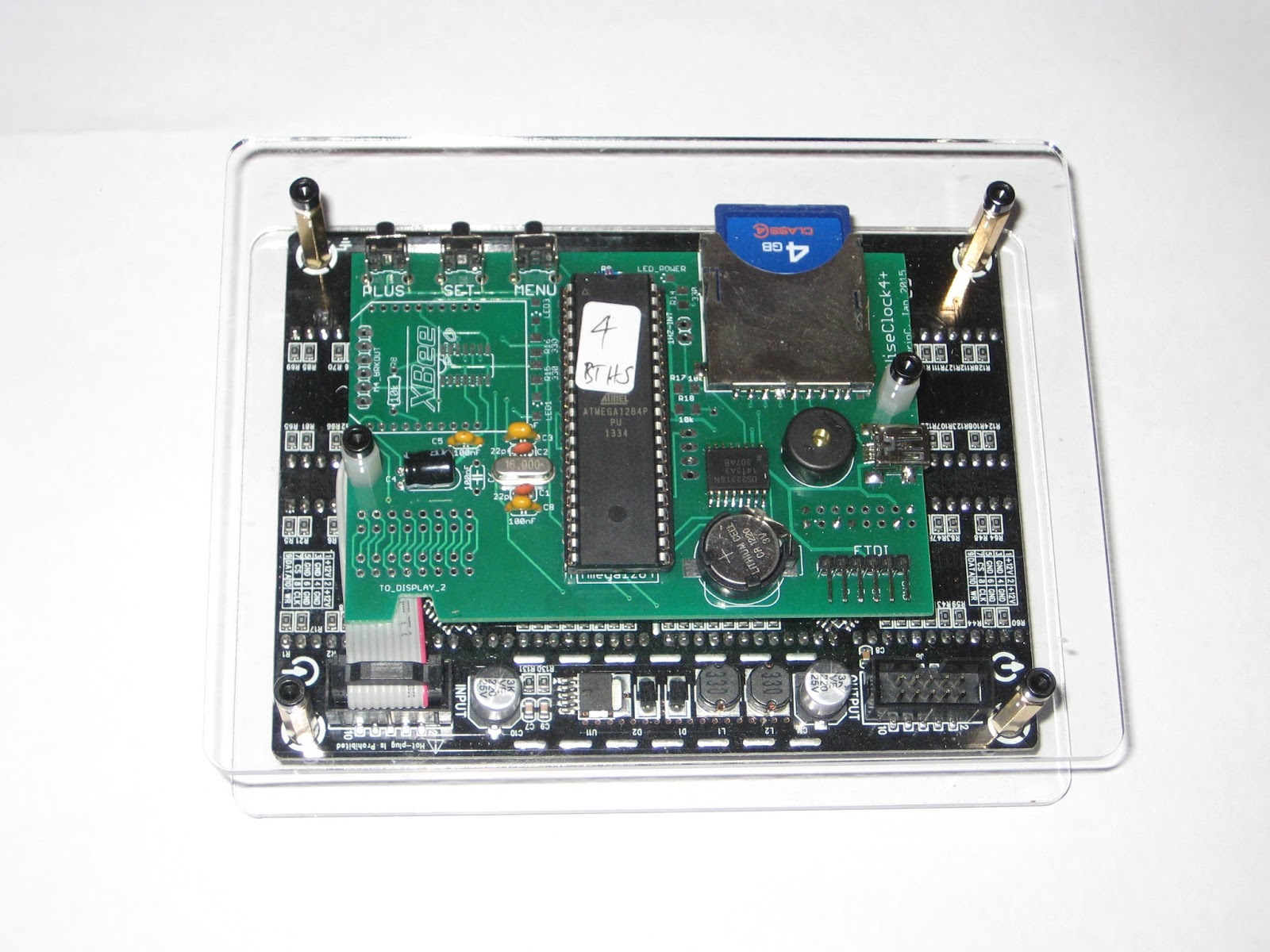
Showing posts with label Wise Clock 4. Show all posts

Wednesday, June 3, 2020

Sure 32x16 bicolor display (HT1632) driven by ESP32

I was recently awoken from the Netflix-infused lethargy by an email from LukeW, who needed help with running the Wise Clock 4 on ESP32. What a great idea that is!

I had an epiphany when I realized what a powerful platform ESP32 is: unbelievable price (about $10 on amazon), serious hardware (memory, speed, WiFi, BT, BLE, multiple USARTs etc.), amazing software support (Arduino IDE, libraries, examples etc.).

The latest Arduino IDE I had was version 1.6.7 (2017). Trying to install the support package for ESP32, I got a security error along the lines:
javax.net.ssl.SSLHandshakeException: sun.security.validator.ValidatorException: PKIX path building failed:
sun.security.provider.certpath.SunCertPathBuilderException: unable to find valid certification path to requested target.

It works fine when downloading it through the browser (https://dl.espressif.com/dl/esptool-2.6.1-windows.zip), meaning that the server certificate that esspressif is using is not recognized by the JVM run by Arduino (folder "java" in the arduino directory). Identifying and adding the certificate to the JVM's keystore is time consuming, so I decided that it is just easier to upgrade to the latest Arduino IDE (currently 1.8.12), installed this time (a first for me) from Microsoft store. Even though the process is seamless, I have no idea where this software was placed (definitely not where I wanted it). I also learned the new way (where have I been for so long?) to include and manage libraries (through the "Add .ZIP library" menu item).

Using the ESP32 devkit is as easy as the first Arduino (Duemilanove). The only thing one needs is a solderless breadboard, which I was lucky to have one around, since I don't remember ever using one before. An interesting fact is that the ESP32 board, inserted in the breadboard I have, leaves room for connecting wires only on one side.


Next step was to connect the Sure 32x16 displays (two, daisy chained). I used these pins:
// pins used to connect to ESP32;
#define HT1632_DATA   12 // Data pin (pin 7 of display connector)
#define HT1632_CS     14 // Chip Select (pin 1 of display connector)
#define HT1632_WRCLK  13 // Write clock pin (pin 5 of display connector)
#define HT1632_CLK    27 // clock pin (pin 2 of display connector)

With only the pin changes, the HT1632 files used in Wise Clock 4 software work perfectly fine with ESP32. They can be found here, called from a test sketch that uses 2 displays (#define NUM_DISPLAYS 2 in file MyHT1632.h).

SD card should be next, using the ESP32 support libraries.
With ESP32, the sky is the limit: hopefully no more program memory limitations, no need for third party libraries (e.g. Sanguino), better support for sound, easier access to WiFi, support for extra peripherals etc. Wow!

It did not take long to test the SD card, using this wiring:

which looks like this on the breadboard:


Running SD_Test.ino sketch example coming with ESP32 libraries on a Wise Clock 4 SD card, this is what serial monitor shows:


Incredible, with no sweat at all, just out of the box. Wow again!

Another small step: modified the SD_Test.ino to read the content of the file, line by line:
void setup()
{
    Serial.begin(115200);
    if(!SD.begin()){
        Serial.println("Card Mount Failed");
        return;
    }
    uint8_t cardType = SD.cardType();

    if(cardType == CARD_NONE){
        Serial.println("No SD card attached");
        return;
    }

  openFile(SD, "/quot1.txt");
}

void openFile(fs::FS &fs, const char * path)
{
    Serial.printf("Reading file: %s\n", path);

    file = fs.open(path);
    if(!file){
        Serial.println("Failed to open file for reading");
        return;
    }
}

char lineBuf[500] = {0};

void readLine()
{
  int i = 0;
  lineBuf[0] = 0;

  while (file.available())
  {
    char c = (char) file.read();
    lineBuf[i++] = c;
    if (c == '\n')  break;
  }
  lineBuf[i] = 0;
}

void loop()
{
  readLine();
  Serial.write(lineBuf);
  delay(1000);
}

And the output, in serial monitor:


Sunday, March 3, 2019

Wise Clock 4 - March 2019 software release

A long overdue (3+ years since the previous one!?) release of the Wise Clock 4 software is finally here. This one compiles on Arduino 1.6.7 (and later) and has a few code improvements, most of them courtesy of MikeM:
  • created a display abstraction layer that will allow porting the display functions away from HT1632 Sure displays, eventually; essentially, any new "compatible" (min 16x32 resolution) display can be supported by implementing the set of functions declared in DisplayBase.h; currently, the HT1632 functions are defined in DisplayHT1632.cpp class;
  • eliminated the need to set the day-of-week, which is now calculated from date (Zeller method);
  • introduced the option to use MiniGPS class instead of TinyGPS, which saves some program memory and also RAM; the improved GPS code uses now a new setting in messages.txt (utc.offset);
  • some bug fixes related to buffer overruns when getting the weather RSS data; Mike discovered this issue after switching to a new weather service (http://www.rssweather.com/zipcode/27612/rss.php), since the old one (e.g. http://w1.weather.gov/xml/current_obs/KRDU.rss) is no longer supported (protocol was changed to https, which cannot be handled by the current ESP8266 class);
As a reminder note (for myself), the ESP8266 and GPS-related changes mentioned above should also find their way into the WiFiChron code, sometime.

Recently, Nick sent this photo of his stack (stash?) of WiFiChrons.


Tuesday, April 26, 2016

From the mailbox

AlexP managed to port the Wise Clock 4 code to Arduino Mega2560 (shared here, thanks Alex!). He made this video demonstrating it in action:


Today I had a great day! I did it! I soldered a development board for my Mega2560. A little corrected code and ... voila!  Wiring diagram:
  • rtc sqw (1hz) - pin 2
  • menu key - pin 3
  • set key - pin 4
  • plus key - pin 5
  • speaker - pin 6
  • speaker - pin 7
  • HT1632_WRCLK - pin 10
  • HT1632_CS - pin 11
  • HT1632_DATA - pin 12
  • HT1632_CLK - pin 13
  • rtc sda - pin 20
  • rtc scl - pin 21
(SD while not tested, but I think it works)
  • sd miso - pin 50
  • sd mosi - pin 51
  • sd sck - pin 52
  • sd cs - pin 53

NelsonC built his own hand-wired version of WiFiChron and it looks awesome:


MikeM sent in (thanks Mike!) his latest WiFiChron code (available here).
The enclosed zip file compiles under Arduino 1.6.8, though it generates a warning I haven't figured out how to eliminate.
Ray ran into a problem with data overruns. When data in an RSS feed was split between multiple packets, sometimes the last few bytes of a packet were dropped from the RSS buffer. I didn't see that problem with my clock when I was developing the code, nor did I see it on the WiseClock4. I've re-built the RSS state machine to be more CPU efficient, and now the packets are processed without drops. We probably don't need to change the RSS code on the WiseClock4 as it runs at 16 MHz and not 8 MHz like the WiFiChron.
I also changed the PROGMEM statements to fit the 1.6.8 standard.

And finally, I got the PCBs for the 1284-equipped versions of WiFiChron and bGeigie nano.
For both I relied on internal (software-driven) pull-ups (basically I eliminated the pull-up resistors), without checking first if that would work. Unfortunately, the current sanguino library does not implement correctly the function pinMode(x,INPUT_PULLUP). So I had to resort to resistors soldered on the back of the board. That, plus missing a necessary decoupling capacitor, plus also missing some connections on the bGeigie board, made for a "fun-filled", but in the end successful, testing. More on these in a future post.

Sunday, April 3, 2016

Wise Clock 4 software for Arduino 1.6.8

Scott H. put the time and the effort to port the Wise Clock 4 code (also the HDSP-Proverb and WiFiChron code) to Arduino 1.6.8 (the latest, but maybe not the greatest). This is a big endeavor, which I did not plan to pursue any time soon. Now, thanks to Scott, here we have it. I compiled it and uploaded it myself, on Windows (he did it on Mac).

The Wise Clock 4 files are all in the same "TheClock" folder, directly under "libraries", as shown in the following screenshot.


But before uploading to ATmega1284, this section needs to be inserted in boards.txt (*):

##############################################
atmega1284.name=Sanguino W/ ATmega1284p 16mhz
atmega1284.upload.tool=avrdude
atmega1284.upload.protocol=stk500v1
atmega1284.upload.maximum_size=129024
atmega1284.upload.speed=57600
atmega1284.bootloader.low_fuses=0xFF
atmega1284.bootloader.high_fuses=0x98
atmega1284.bootloader.extended_fuses=0xFD
atmega1284.bootloader.path=atmega
atmega1284.bootloader.file=atmega1284p_16MHz.hex
atmega1284.bootloader.unlock_bits=0x3F
atmega1284.bootloader.lock_bits=0x0F
atmega1284.build.mcu=atmega1284p
atmega1284.build.f_cpu=16000000L
atmega1284.build.core=sanguino
atmega1284.build.board=AVR_ATMEGA1284
##############################################

The two highlighted lines are new for 1.6.8: "upload.tool" and "build.board" (which has a default value though).

Next, as specified in the line "atmega1284.build.core=sanguino", we need to create the folder "sanguino", containing the core files. Folder structure should look like this:


Note that a few sanguino core files that worked in Arduino 1.0.6 need to be modified to compile on 1.6.8. Like the Wise Clock 4 code itself, most of these changes are related to the PROGMEM definition, which now requires every progmem variable to be constant. The modified files are WString.* and Print.*, copies of the arduino core files.

Talking about sanguino core files, which served pretty well so far, it is worth mentioning that the current implementation for pinMode(pin, INPUT_PULLUP) (in file wiring_digital.c) is not working. Until I find a software solution, I will still need to use pull up resistors.


(*) There is a more "user friendly" way to add a new board, that involves downloading packages from a specified URL, but I found the learning curve for this method too steep (or, to say it differently, I was too lazy).

Saturday, March 19, 2016

A recap of Wise Clock 4 features

The list of code changes and new features at the top of the source files (see WiseClock.cpp, for example) grows longer and longer. I thought of getting this list out in the open, for the people who are not particularly interested in the C++ code or just don't want to look at the source code (or release notes file for that matter, not updated in a long while though) to find out what Wise Clock 4 can do.

1. First and foremost, Wise Clock 4 displays quotes retrieved from text file(s) stored on SD card, with both  FAT16 or FAT32 file systems being supported. This piece of functionality is still the core of the software.

2. Secondly, Wise Clock 4 displays the time retrieved from DS3231 extremely accurate real time clock chip. (These first two features inspired its name: "wise" and "clock" :)

3. The display is tri-color (red, green, orange) LED matrix with a minimum resolution of 16x32 and a maximum of 16x128. Currently, the resolution is hard-coded, meaning that the software is compiled and built for a specific display and it cannot be changed dynamically (by the user, from buttons or configuration settings, although this may be a future enhancement);

4. Time can be shown in:
  • various display modes:
    • Pacman;
    • Pong;
    • Words;
    • TIX;
    • Unix;
    • binary;
    • BIG;
    • Quotes (time displayed along with scrolling text);
    • "close enough" (approximate), showing passed minutes pie-chart;
    • dual time-zone analog display, with hour and minute hands "rotating" inside round face;
  • most formats:
    • just hours and minutes or
    • hours, minutes and seconds, or
    • even tenths of a second for chronometer;
    • 12 or 24 (military) hour format;
  • different sizes:
    • medium, on the bottom half of the screen;
    • big, scrolling across or rolling digits or
    • tiny, when more digits need to fit on the screen.
5. Beside clock, Wise Clock 4's other time-related functions:
  • alarm;
  • stop watch (chronometer);
  • count down timer;
  • project time clock;
  • GPS-based time synchronization (requires GPSBee module to be installed);
  • NTP-based time synchronization (requires Esp8266 Wee/WiFly module to be installed);
  • scoreboard (as a separate, independent, standalone, software);
  • time lived since birth;
  • chime every half hour;
  • show night and day on a global map (requires map overlay, see this post);
  • show the current time at up to ten different cities, cycling through each city;
  • show messages predefined for specific days (e.g. birthday/holiday wishes, event reminders etc.) recorded in message.txt file on SD card;
  • automatic, configurable (in SD file) "night" mode for display (saves power and LEDs, produces less light at night);
  • automatic and configurable (SD file) Daylight Savings Time;
6. Wise Clock 4 functions not related to time:
7. Other Wise Clock 4 features:
  • manual (press "Plus" button) or auto dimming (with LDR) of the display brightness;
  • manual (press "Set" button) adjustment of the speed for text-scrolling;
  • remote control using 4-button keyfob;
  • uses different colors to indicate how close the alarm is to go off (red two hours before, orange before that);
  • define and display quotes, partially or entirely, in different colors;
  • select a mode ("app") to start at power on;
  • select one of the many different fonts;
  • post sensor data to monitoring web site;
  • display info retrieved from the web (through WiFi), e.g. stock quotes, weather data etc.
  • can be used as electronic commercial signage for advertisement, news, announcements etc. due to its high visibility/readability and ease to set up and configure;
  • can be used in competitions or sporting events, to display timing and/or info, visible from both sides of the finish line (see Kandisky clock).
8. A vast tree of menu items, allowing the user to access its many functions easily, to choose the time-display mode, to set values (e.g. time) and/or parameters (e.g. amount of time for a countdown) and to save settings (e.g. the app running at power on).

The menu is split into two loops: one for settings, the other one for apps.
  • Settings menu items are: APPS, ALARM, AL+/AL-, DATE+/DATE-, REMI+/REMI-, TEMP+/TEMP-, MESG+/MESG-, CHME+/CHME-, FONT+/FONT-, CELS/FAHR, 24H+/24H-, DST+/DST-, TIME, Y M D, DAY, NGHT+/-, LOG+/-, ANIM+/-, PWRON.
  • Apps menu items are: SETUP, QUOTE, BIG, TIX, CNTDN, STOPW, WORDS, SCORE, PONG, PACMN, CHRON, RACER, UNIX, LIVED, TCLOK, UTC, LIFE, DEMO, STATS, NEWSD.
Selecting the "SETUP" menu entry will take you to the Settings menu loop, selecting the "APPS" menu entry will take you to the Apps menu loop.

Each app can use the buttons "Plus" and "Set", with button "Menu" always being used to trigger the display of the menu.
The buttons "Set" and "Plus" have different functions for different apps. For example, in SCORE, one of the simplest apps, each button increments the score for one side/player; in CHRON, "Set" moves from one function to the other, with "Plus" triggering that function (e.g. increment the number of hours).
Menu navigation is intuitive and easy to understand after playing with the buttons a little bit.

9. From the source code perspective, the Wise Clock 4 software is modular, flexible and extensible (see this mod, for example), based on a framework (implemented in WiseClock.cpp) and multiple "applications" (files named App*.cpp) that can be enabled/disabled (included in/excluded from the software) at build-time by macro definitions (e.g. #define) and activated/executed at run time.


Add light sensor to Wise Clock 4

This is long overdue.
As we know, the display brightness on Wise Clock 4 can be changed between 5 levels, by pressing the "Plus" button. To adjust the brightness automatically, based on the light conditions, we need to add a light-sensitive sensor of some sort, and the most common is the LDR (light-dependent resistor).
Any of the countless articles and tutorials on Arduino + LDR will teach how to connect the LDR to an analog pin, using a voltage divider. For Wise Clock 4, the LDR is connected between A0 (pin 40 of the processor) and ground, with a 10k resistor between A0 and Vcc, as shown below:

  GND|----[ LDR ]---A0---[10k resistor]----+Vcc

The automatic brightness adjustment is enabled in software with this macro (in file UserConf.h):

// use an LDR (connected to A0) to automatically adjust
// (every 5 seconds) screen brightness to ambient light;
#define AUTO_BRIGHTNESS

and implemented in this new function:

void WiseClock::checkBrightness()
{
#ifdef AUTO_BRIGHTNESS
  // adjust brightness every 5 seconds;
  if (millis() - lastCheck > 5000)
  {
    int ldrValue = analogRead(0); // A0
    byte brightLevel = map(ldrValue, 0, 1023, MAX_BRIGHTNESS, 0);
    if (nBrightness != brightLevel)
    {
      nBrightness = brightLevel;
      setBrightness(brightLevel);
    }
    lastCheck = millis();
  }
#endif
}

called from the main loop (TheClock.ino):

void loop()
{
unsigned long ms = millis();

checkSound(ms);
wiseClock.checkSerial();
wiseClock.checkScroll(ms);

if ((long)(ms - wiseClock.nextRun) >= 0)
{
alarmClock.getTimeFromRTC();
alarmClock.checkAlarm();
wiseClock.checkMenuActive();
wiseClock.runCrtApp();
}

wiseClock.checkBrightness();
}

It really doesn't get much simpler than this.

I also considered other hardware solutions (and actually bought the parts):
- I2C light sensor TSL2561
but I did not follow through after I saw how effective (and so much cheaper) the LDR is.

Monday, February 29, 2016

Hockey scoreboard

What's missing from this picture (of a backyard hockey rink)?


You got it (probably the post title helped too): a scoreboard.
For those not familiar, a traditional one looks like in the photo below (click on it to see it bigger).


It may look simple, but it provides a lot of functionality:
  • display 2-digit home score;
  • display 2-digit visitor score;
  • countdown timer, with the starting time configurable/settable; timer displays mostly minutes and seconds, but under 1 minute, it displays seconds and tenths of a second;
  • stop/resume the countdown;
  • display round/period; number of periods is configurable/user-settable;
  • buzzer sounding at the end of the round, game or on demand;
  • penalty timers for up to four players (that also stop/resume with the main timer);
  • functions as a clock when not used in a game.
The control for the hockey scoreboard is pretty complex too. The control console is usually wired to the scoreboard. Sometimes the console is detachable (brought in to the booth by the score keeper), connected to a cable that plugs in.

An easy and quick way to build a home-made hockey scoreboard is to re-program a dual-display (16 x 64 pixels) Wise Clock 4. The scoreboard should be controlled wirelessly, from a distance of at least 10 meters (which disqualifies infrared remotes and also the most common Bluetooth, "class 2"). Potential solutions for the scoreboard remote control are:
  1. XBee
    • good distance range;
    • not cheap;
    • reliable communication;
    • requires building and programming a remote control device;
    • already hardware-supported by Wise Clock 4 board;
  2. RFM-12
    • good distance range;
    • cheap;
    • reliability probably ok for short messages;
    • requires building and programming a remote control device;
    • uses SPI interface, requiring some hardware hacking;
  3. RF 4-button key fob
    • cheap
    • easy to integrate
    • does not require any software support;
    • reliability at distance greater than 10m (?);
    • no need to build the remote control;
    • unfortunately limited to only 4 buttons;
  4. WiFi
    • cheap (ESP8266)
    • works as access point; user connects from smart phone or tablet, to access HTML form pages to type/input commands;
    • requires extra coding;
    • no need for extra remote control device (since using phone or tablet);
For the user, the easiest way to control the scoreboard would be by pressing physical buttons (the other, less-friendly, way would be by entering/selecting messages, e.g. "STOP", or "resume").

If using buttons, at least 4 are required to cover the minimum functionality:
  • reset scoreboard - D0;
  • start/stop/resume countdown timer - D1;
  • increment home score - D3;
  • increment visitor score - D2 (available) or D22 (re-routed)
which makes the 3rd solution above (RF 4-button key fob) an easy pick.

This is how the prototype scoreboard works on my desk:


The software is a branch-out of the Wise Clock 4 main software (using the same libraries, classes and functions, but in a separate .ino file). I created a new font (file fontFull.h) for the score digits, defined in a 8x16 matrix.
To add extra features ("clock mode", "chrono mode", message scrolling etc), more buttons/commands would be required on the remote control. Which means that the RF 4-button key fob is barely enough for now, and another solution must be implemented. My next favourite is the RFM-12, a topic for a future post.

Saturday, February 20, 2016

Add a barometer sensor to Wise Clock 4

While cleaning up my desk, I found a little I2C module that I completely forgot about. It is a breakout for BMP180 barometer sensor, which I probably bought on ebay for a couple of dollars (I just checked, it is still under $2). This tiny board can be added literally to any Arduino clock to display atmospheric pressure, with the help of Adafruit_BMP085 library.

Connecting the barometer to Wise Clock 4 is trivial: I soldered wires directly to processor pins (SDA, SCL, VCC and GND), as shown in the photo. There is plenty of clearance between the board and the display.


In the software, as mentioned, I used the Adafruit BMP085 library, which also covers the compatible BMP180. There is no extra setting required from the user: the pressure is displayed together with the temperature, and enabled/disabled from the TEMP+/- menus. Also, there is no extra settings when compiling/building: if the BMP180 module is not installed, no pressure data will be displayed.

Essentially, the new code consists of 2 functions added to the AppTmp class:

boolean CAppTmp::initBarometer()
{
  bmp = new Adafruit_BMP085_Unified(10085);
  isBaro = bmp->begin();
}

int CAppTmp::getPressure()
{
  int pressure = 0;
  if (isBaro)
  {
sensors_event_t event;
bmp->getEvent(&event);
    if (event.pressure)
{
  pressure = event.pressure;
}
  }
  return pressure;
}      

Another nice thing about BMP180 is that it can also provide the temperature. But, like DS3231, it seems to be a little off compared with a regular thermometer sitting nearby.

Next, I will try to attache the little barometer to wsduino in an aesthetically pleasing manner, probably in the empty space in the top left corner.

Sunday, February 14, 2016

New Wise Clock 4 software release

The latest release of the Wise Clock 4 software can be found here.

It includes a few new features:
The WiFi settings are configured in the SD card file message.txt, and they look like this:

#### ESP8266 configuration
#
# Esp8266.ssid Wireless SSID to connect to
# Esp8266.phrase pass phrase to use (WPA authentication)
# Esp8266.sntp optional SNTP server IP address (not hostname) for time synchronization
# Esp8266.rssurl optional URL of an RSS feed, like http://w1.weather.gov/xml/current_obs/KMYF.rss

Esp8266.ssid   BELL475
Esp8266.phrase 7xyz1E9F6
Esp8266.sntp   
Esp8266.rssurl 

This feature is enabled in the code by the following line in file UserConf.h:
#define WANT_ESP8266
  • support for GPSBee (from seeedstudio): only the minutes and seconds are set from the GPS data, the hours remain as set from the buttons; synchronization is performed once a day and/or when the clock is reset (powered off-on);
To enable this feature, make sure the following line in UserConf.h is not commented out:
#define WANT_GPS
  • "Night" mode: turns the display off at night, between the hours set in message.txt file, as shown:
#### turn display off at night (in conjunction with menu "NIGHT");
#### formatted as HHMM (military time);
Night.start 2230
Night.end   600

This feature is enabled/disabled from the NIGHT+/- option in the SETUP menu. In Night mode, the display shows just a random dot. The implementation is in AppNight.class, and can be changed to display any desired effect (e.g. Bezier splines, Lissajous curve etc).
  • "Unix time" mode: displays advancing Unix time (passing seconds from Jan 1, 1970); accessed through the "UNIX" menu option.
Also, debugging (sending messages to Serial port) is now controlled by a single line in UserConf.h:
#define _DEBUG_

Before compiling and uploading the software, make sure the debug macro above is commented out (since it is not in the code you just downloaded). With the debug disabled, the code runs faster and takes less memory space.


Tuesday, July 7, 2015

Wise Clock 4 with the new 3mm 3216 LED display from Sure

My inventory of "old" 3216 3mm displays from Sure Electronics is now depleted. As everybody already knows by now, Sure redesigned the display to be powered with 12V instead of 5V (plus a few other cosmetic changes).
The Wise Clock 4 board cannot be plugged into the new display's connectors anymore, since they are now different (10 pins instead of 16), and the assignment of signals to pins has changed as well.

Making a seamless Wise Clock 4 with the new display is still possible, with a little more soldering work. The board will be connected to the display using the ribbon cable provided. To do this, cut one connector off the ribbon cable, then solder 5 wires (4 signal + ground) from the cut end of the ribbon, in the place of the header, as shown in the photo below.


The 5V power line from the clock's board (red wire in the photo) will be soldered separately from the ribbon cable, bypassing the display's 5V regulator, as shown in the next photo.


The new display is "top heavy", that is, it has the connectors and the 5V regulator (with large capacitors and inductors) at the top. These may interfere with the clock's buttons and the SD card. To avoid touching them accidentally, it is better to position the display upside down, as shown in the next photo.


For this reason, the sketch needs a little tweaking: all pixel-related functions in HT1632.cpp file will have to change the coordinates, like this:

void ht1632_plot (coord_t x, int8_t y, byte color)
{
#ifdef WANT_UPSIDE_DOWN
  x = X_MAX-1 - x;
  y = Y_MAX-1 - y;
#endif
...
}

The macro WANT_UPSIDE_DOWN is defined in UserConf.h.

Also notice that the Wise Clock 4 board is now mechanically  fixed to the back panel (because it's not plugged in the display's connectors anymore).
Needless to say that the laser-cut plates for the two version of the displays are not compatible, since the displays' dimensions are different.


I will continue to provide a "complete kit" that includes the new display, the 2 plates, and the screws + standoffs. The back plate won't have the 2 holes (for the board) drilled though. This "complete kit" may not have the two 2x8 female headers (since they are not needed, and will even be detrimental). In case the headers are in the kit, DO NOT SOLDER THEM if you use the new display.
The processor in the "complete kit" will be loaded with the sketch for the new display, with the software modification mentioned above.

Wednesday, June 24, 2015

WiFiChron fix and other WiFis

The peculiar feature of the "May 2015" revision of WiFiChron board is that it was designed to use software serial to communicate with either the XBee or ESP module. The reason is related to debugging. I wanted to be able to send messages to the serial monitor while (software serially) communicating with the serial device. This solution works well for XBee (GPSBee, BTBee), but not for ESP8266, only because the software takes more than the available 2K of RAM in this case (WiFi + software serial).

The immediate fix to use the ESP module is to connect its Rx/Tx lines to Rx/Tx of the processor. The existing connections can be left uncut, since they are not used in the sketch for ESP8266. The wiring should be like in the photo below.


The "permanent" fix would be re-designing the board to use ATmega1284 SMD (DIP-40 would not fit).

Talking about 1284, take a look at Farit's WiseClock4 mod. He used the WiseClock4 board, but completely re-wrote the software, including, it seems, the definition of new fonts. The SD card is now used for storing MIDI files (among others) that can play tunes through the Fluxamasynth shield.


A few of the other hardware and software features are:
  • WiFi access to the internet through WiFly module;
  • accurate time keeping through NTP;
  • display weather forecast read from the web;
  • daily alarms;
  • automatic adjustment of the display brightness with light sensor;
  • user-selectable display color.
The exquisite and elaborate wooden enclosure adds even more character.

And a photo of the internals, with the extra hardware:


Farit also shared the software he wrote, hopefully an inspiration for future mods.

Wednesday, September 24, 2014

Adding RF remote control to Wise Clock 4

Nick asked me once about adding remote control to his mega wise clock, similar to those pictured here (or any wise clock that may hang on a wall, for that matter). An obvious way to quickly and easily do this is by wiring the "simple RF M4 receiver" from adafruit to the 3 buttons of the Wise Clock. This 315MHz receiver module works in conjunction with the 4-button keyfob, also from adafruit. Note that the receiver comes in 3 flavors: momentary, toggle and latch. The one that "simulates" the touch buttons is the momentary one, hence the "M4" in the name (momentary, 4 outputs).

The schematic I used to connect the receiver module to the Wise Clock board is shown below.


I tested it and it works fine. Almost always :)
That is, ALWAYS when the display is not plugged in the clock board, NEVER when the display is connected. Which led me to conclude that either the display emits in the 315 MHz band (interfering with the receiver module; which it didn't; I checked by shielding the receiver in a metal case, wire antenna out), or it gets the power too dirty for the receiver.

An oscilloscope would have quickly answered my question. But since I don't have one, I tried all kinds of power adapters (from the fake-$1-on-ebay iPhone ones, to genuine 2A Samsung), up to batteries (4xAA). Incredibly, only the latter did the trick. Again, to emphasize, this is ONLY when the 3216 display is connected.

Below are some photos of the setup.


Note how the receiver is powered directly from the AA batteries. There is a common ground with the clock board though (black wire).


The LEDs are not mandatory, I added them just for visual feedback. They light up when either the board's or keyfob's buttons are pressed.

In any case, using the batteries to power the module is just to prove that this solution works. To be practical, I should add a DC-DC step-up voltage converter. According to the PT2272 datasheet (the chip on the M4 receiver), the module can be powered from 5V to 10V. I am not sure a boost converter would work in this case, unless it outputs really clean voltage, but it's the only practical solution I see at the moment.

Once I have this figured out, I plan on designing a small add-on board. The receiver module will plug into this add-on board, which will be connected to the Wise Clock's board through 5 wires.

As always, feedback (and help) is greatly appreciated.


PS I forgot to mention that I tried filtering the power with capacitors, up to 1000uF, with no success. (The 2-pin female header where the battery wires are plugged in were initially used to insert different capacitors.)


Sunday, July 6, 2014

July 2014 release of Wise Clock 4 software

This latest code release includes:
  1. introduction of the two-faced (Kandinsky) feature, on 2 or 4 displays;
  2. fixes related to screen centering for 3 or 4 displays (Big, Stopwatch etc);
  3. fix for Pacman app on 3/4 displays;
  4. fix for Words app on 3/4 displays (so the text does not start scrolling in the middle of the screen);
  5. improved the font definition for digits (effectively making them 5x7 pixels; see photo below);
  6. fix for Score app (swapped button functions);


I am sure that there are still a few bugs to fix.
As well, some improvements would be nice, the most notable being the better use of a screen with 3 or 4 displays, especially for the Big mode, where the time is still shown on the (center) 2 displays. (This would call for spreading out of the digits, or even the definition of a wider font.)


(One of the displays in the 3-display clock is faulty, hence the missing pixel in the bottom 1.)

Sunday, June 22, 2014

Wise Clock chronometer completed

As I briefly mentioned in my previous post, I re-started working on the Wise Clock chronometer. That old version only displayed the time from the RTC, and lacked basic user functions like setting the time from buttons. Even though it was called "chronometer" it did not have a proper timer functionality (besides showing the time with seconds).

I implemented the new software(*) (available here) as a state machine, easy to describe, understand and upgrade. Below is the diagram with the states and transitions.


This clock uses the same board as Wise Clock 4, but a jumper connects SQW of DS3231 to D2 (INT2 interrupt pin of ATmega1284). This allows the software to take advantage of an ISR being called every second, which in turn updates the time on the display. Because this approach is in contrast to the existing Wise Clock 4 software (which did polling on RTC to update the time on the screen), its integration into the main trunk would be difficult, if not impossible.

In any case, the state machine "framework" can be replicated to most devices that can be described as a set of states with transitions between them. For example, for a device with 3 buttons like Wise Clock 4, the "framework" consists of 5 important functions:

1. the main loop() that checks the actions on the buttons;

void loop()
{
  int userAction = plusButton.checkButton();
  if (userAction != NO_ACTION)
  {
    // SET button was pressed;
    processPlusButton(userAction);
  }
  else
  {
    userAction = setButton.checkButton();
    if (userAction != NO_ACTION)
    {
      // SET button was pressed;
      processSetButton(userAction);
    }
    else
    {
      userAction = menuButton.checkButton();
      if (userAction != NO_ACTION)
      {
        // MENU button was pressed;
        processMenuButton(userAction);
      }
    }
  }
  executeState();
}

2. the function executeState(), which implements the functionality of each individual state;

void executeState()
{
  switch (crtState)
  {
    case STATE_SHOW_TIME:
      if (bUpdate)
      {
        bUpdate = false;
        getTimeFromRTC();
        displayDynamicTime(hours, minutes, seconds, &lastHour, &lastMin, &lastSec);
      }
      break;

    case STATE_COUNTDOWN:
      if (bUpdate)
      {
        bUpdate = false;
        if (isCountdownInProgress)
        {
          calculateTimeLeft();  // set cHours, sMinutes, cSeconds;
          displayDynamicCountdown(cHours, cMinutes, cSeconds, &lastCHour, &lastCMin, &lastCSec);

          if (cHours==0 && cMinutes==0 && cSeconds==0)
          {
            // countdown ends;
            isCountdownInProgress = false;
            showStaticTime(0, RED, 0, RED, 0, RED);
            beep();
          }
        }
      }
      break;

    case STATE_SET_TIME_HOUR:
      showStaticTime(hours, RED, minutes, crtColor, seconds, crtColor);
      break;

    case STATE_SET_TIME_MIN:
      showStaticTime(hours, crtColor, minutes, RED, seconds, crtColor);
      break;

    case STATE_SET_TIME_SEC:
      showStaticTime(hours, crtColor, minutes, crtColor, seconds, RED);
      break;

    case STATE_SET_CNTDWN_HOUR:
      showStaticTime(cHours, RED, cMinutes, ORANGE, cSeconds, ORANGE);
      break;

    case STATE_SET_CNTDWN_MIN:
      showStaticTime(cHours, ORANGE, cMinutes, RED, cSeconds, ORANGE);
      break;

    case STATE_SET_CNTDWN_SEC:
      showStaticTime(cHours, ORANGE, cMinutes, ORANGE, cSeconds, RED);
      break;
  }
}

3. one processing function per button (hence 3 functions: processPlusButton(), processMenuButton(), processSetButton()), each describing the transitions from every state based on user input;

void processPlusButton(int userAction)
{
  switch (crtState)
  {
    case STATE_SET_TIME_HOUR:
      if (userAction == BTN_PUSH)
      {
        hours++;
        if (hours>23) hours = 0;
      }
      break;

    case STATE_SET_TIME_MIN:
      if (userAction == BTN_PUSH)
      {
        minutes++;
        if (minutes>59) minutes = 0;
      }
      else if (userAction == BTN_DBL_PUSH)
      {
        minutes = minutes + 10;
        if (minutes>59) minutes = 0;
      }
      break;

    case STATE_SET_TIME_SEC:
      if (userAction == BTN_PUSH)
      {
        seconds++;
        if (seconds>59) seconds = 0;
      }
      else if (userAction == BTN_DBL_PUSH)
      {
        seconds = seconds + 10;
        if (seconds>59) seconds = 0;
      }
      break;

    case STATE_SET_CNTDWN_HOUR:
      if (userAction == BTN_PUSH)
      {
        cHours++;
        if (cHours>23) cHours = 0;
      }
      break;

    case STATE_SET_CNTDWN_MIN:
      if (userAction == BTN_PUSH)
      {
        cMinutes++;
        if (cMinutes>59) cMinutes = 0;
      }
      else if (userAction == BTN_DBL_PUSH)
      {
        cMinutes = cMinutes + 10;
        if (cMinutes>59) cMinutes = 0;
      }
      break;

    case STATE_SET_CNTDWN_SEC:
      if (userAction == BTN_PUSH)
      {
        cSeconds++;
        if (cSeconds>59) cSeconds = 0;
      }
      else if (userAction == BTN_DBL_PUSH)
      {
        cSeconds = cSeconds + 10;
        if (cSeconds>59) cSeconds = 0;
      }
      break;

    case STATE_SHOW_TIME:
      if (userAction == BTN_PUSH)
      {
        // change brightness;
        incrementBrightness();
      }
  }
}

void processMenuButton(int userAction)
{
  ht1632_clear();
  switch (crtState)
  {
    case STATE_SHOW_TIME:
      if (userAction == BTN_PUSH)
      {
// push MENU button to start setting up the start time for countdown;
        crtState = STATE_SET_CNTDWN_HOUR;
      }
      else if (userAction == BTN_HOLD)
      {
        crtState = STATE_SET_TIME_HOUR;
      }
      break;

    case STATE_SET_TIME_HOUR:
    case STATE_SET_TIME_MIN:
    case STATE_SET_TIME_SEC:
      if (userAction == BTN_PUSH)
      {
//----------------------------------------------------------------
// pressed the MENU button while setting the time;
// exit setting the time and resume time showing;
//----------------------------------------------------------------
        // save the time;
        setRtcTime();
        // return to the main screen (showing the time);
        crtColor = GREEN;
crtState = STATE_SHOW_TIME;
        showStaticTime((is24Hmode? hours : hours%12), crtColor, minutes, crtColor, seconds, crtColor);
        // also update the lastSec (for smooth rolling);
        lastSec = seconds;
      }
      break;

    case STATE_SET_CNTDWN_HOUR:
    case STATE_SET_CNTDWN_MIN:
    case STATE_SET_CNTDWN_SEC:
      if (userAction == BTN_PUSH)
      {
//----------------------------------------------------------------
// pressed the MENU button while setting the countdown time;
// exit setting the countdown time and start the countdown now;
//----------------------------------------------------------------
        isCountdownInProgress = true;
// total number of seconds for countdown;
cntDownTime = (long)((cHours * 3600l) + (cMinutes * 60) + cSeconds);
        // start displaying the countdown;
        crtColor = ORANGE;
        showStaticTime(cHours, crtColor, cMinutes, crtColor, cSeconds, crtColor);
        crtState = STATE_COUNTDOWN;
      }
      break;

    case STATE_COUNTDOWN:
      // pressing MENU while counting down will revert to normal clock mode;
      isCountdownInProgress = false;
      cHours = cMinutes = cSeconds = 0;
      // return to the main screen (showing the time);
      crtColor = GREEN;
      crtState = STATE_SHOW_TIME;
      showStaticTime((is24Hmode? hours : hours%12), crtColor, minutes, crtColor, seconds, crtColor);
      break;
  }
}

void processSetButton(int userAction)
{
  switch (crtState)
  {
    case STATE_SET_TIME_HOUR:
      if (userAction == BTN_PUSH)
      {
        crtState = STATE_SET_TIME_MIN;
      }
      break;

    case STATE_SET_TIME_MIN:
      if (userAction == BTN_PUSH)
      {
        crtState = STATE_SET_TIME_SEC;
      }
      break;

    case STATE_SET_TIME_SEC:
      if (userAction == BTN_PUSH)
      {
        crtState = STATE_SET_TIME_HOUR;
      }
      break;

    case STATE_SET_CNTDWN_HOUR:
      if (userAction == BTN_PUSH)
      {
        crtState = STATE_SET_CNTDWN_MIN;
      }
      break;

    case STATE_SET_CNTDWN_MIN:
      if (userAction == BTN_PUSH)
      {
        crtState = STATE_SET_CNTDWN_SEC;
      }
      break;

    case STATE_SET_CNTDWN_SEC:
      if (userAction == BTN_PUSH)
      {
        crtState = STATE_SET_CNTDWN_HOUR;
      }
      break;

    case STATE_SHOW_TIME:
      if (userAction == BTN_DBL_PUSH)
      {
        // change from 24H to 12H mode and viceversa;
        is24Hmode = !is24Hmode;
      }
      else if (userAction == BTN_PUSH)
      {
        // change font while showing time;
        crtFont++;
        if (crtFont >= NUMBER_OF_FONTS) crtFont=0;
        ht1632_clear();
      }
      else if (userAction == BTN_HOLD)
      {
        // change display mode between rolling and replace;
        displayMode++;
        if (displayMode > 1) displayMode=0;
      }
      // force screen refresh;
      showStaticTime((is24Hmode? hours : hours%12), crtColor, minutes, crtColor, seconds, crtColor);
      break;
  }
}

I did not use timeouts in the current state machine. I thought that timeouts would complicate the user experience, considering that one of the most important functions is the input of countdown time. Timing out from that input was not an option, I think. Therefore, the user is not forced to set up the time in a certain interval.

(*) NOTE: I developed the current software using Arduino 22 (because I started from the old version and I was too lazy to copy it over). To port to Arduino 1.0 and above, the "include WProgram.h" needs to be changed. But you already know the drill :)