Thursday, August 25, 2011

New in store: Bi-color LED mini-display shield

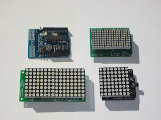
This is my third and newest LED display shield for Arduino. It features two 8x8 RG (red/green/orange) 3mm LED matrices and it has the Arduino form factor, so it stacks perfectly on top of an Arduino 2009/Uno.

This Bi-color LED mini-display shield uses a similar schematic as my other Dual LED matrix shield, based on four 595 shift registers and a driver, in SMD package. The two 8x8 RG LED matrices plug into the machined (round) female headers.


The photo below shows all 3 LED shields together for size comparison, along with an Wiseduino. The "LED mini-display shield" introduced here is in the top-right corner. (All other shields in the photo are sold out.)


This LED mini-display shield also features 2 right-angle micro push buttons.


The LED mini-display shield comes fully assembled and tested.


  (US$35, free shipping to North America)


  (US$40, free shipping outside North America)


The LED mini-display shield can be seen in this video, plugged into an Arduino running a test sketch.


The source code used in this demo can be found here.

Images of the schematic (download Eagle file) and board (download Eagle file) can be seen below.


Tuesday, August 23, 2011

Wise Clock 3 User manual

Update Mar 24, 2011
New features have been added in the Dec 2011 release, see this post.


I was finally able to put together a brief "user manual" for Wise Clock 3, which is also the last step of my "Wise Clock 3" instructable.

Here it is, below, cut and pasted from the instructable.

Wise Clock 3 has 3 buttons, named (in the silkscreen on the board) "Menu", "Set" and "Plus". The "Menu" button is the rightmost one as you face the clock, "Set" is the middle button.

By pressing the "Menu" button, the menu options are shown at the top of the screen, in sequence. A menu option is selected by pressing the "Set" button. Some of the menu options (e.g. "Time", "Date") allow the user to set values, for example the time, the date etc. To increment these values, the user presses button "Plus".


1. Set up the time
 - press "Menu" repeatedly until the option "TIME" is shown;
 - press "Set": now, one of either hours or minutes will start blinking;
 - press "Plus" to increment the blinking value; for hours, next value after 23 is 0; for minutes, next value after 59 is 0;
 - to change between setting (blinking) hours and minutes, press "Set";
 - after the desired time is set (values for hours and minutes are on display), wait about 4 seconds for the blinking to end; this is the time now stored by the clock.
Note: The value for seconds is always set to 0 every time the value for hours or minutes is incremented.


2. Set up the date
 - press "Menu" repeatedly until the option "DATE" is shown;
 - press "Set": the top part of the display will show "Y M D", and the bottom part will show the date, in the format "YYMMDD" (year/month/day);
 - press "Plus" to increment the blinking value; for years, next value after 50 is 0; for months, next value after 12 is 1; for days, next value after 31 is 1;
 - to change between setting (blinking) year, month and day, press "Set";
 - after the desired date is set (values for year, month and day are on display), wait about 4 seconds for the blinking to end; this is the date now stored by the clock.


3. Set up the day-of-week
 - press "Menu" repeatedly until the option "DAY" is shown;
 - press "Set": now the bottom half of the display will show the first three letters of the day of the week (e.g. Mon, Tue etc);
 - press "Plus" to increment the day;
 - after the desired day is reached (shown on display), wait about 4 seconds and the "DAY" option will be exit automatically; this is the day now stored by the clock.


4. Set display brightness
Every time the "Set" button is pressed in one of the main display modes ("Quotes", "Pong", "Pacman", "Big"), the brightness of the LEDs increases one level (out of 5 levels); next after the highest brightness level is the lowest level.


5. Set quote scrolling speed
To increase the speed of the scrolling, press the "Plus" button when in the mode "Quote". There are 5 speeds. Next after the highest speed comes the slowest.


6. Display modes
Changing the display modes is done by pressing the "Menu" button, then selecting the mode shown by pressing the button "Set".
The main mode is "Quote", which displays scrolling quotations, read from SD card, on the half top of the screen.

Other modes are:
 - "Pacman" - Pacman passes by every minute;
 - "Pong" - as in the old-days tennis game console; hours and minutes are displayed on both sides of the net, at the top of the screen, and change when a player "loses", every minute, of course;
 - "Big" - hours, minutes and seconds are displayed on the whole screen, in may different fonts;
 - UTC (universal time), useful for radio amateurs;
 - "Score" - allows keeping the game's score between two players, between 0 and 99.


7. Clock settings (options)
 Beside the current time, Wise Clock 3 can also display:
 - current date, formatted as "Month Day, Year"; this setting is enabled/disabled through the "DT+"/"DT-" menu options.
- temperature, in both Celsius and Fahrenheit; this setting is enabled/disabled through the "TEMP+"/"TEMP-" menu options.
- a personalized, user-editable message, read from SD card (e.g. "Happy Birthday dear John"); this setting is enabled/disabled through the "MESG+"/"MESG-" menu options.
- reminders for special events (anniversaries, Christmas etc), also user-editable on SD card; this setting is enabled/disabled through the "REMI+"/"REMI-" menu options.
- hours as maximum 12 or 24; this setting is enabled/disabled through the "24H+"/"24H-" menu options;
- enable/disable chime (short beep at the bottom of the hour, double beep at the top of the hour), by selecting "CHME+"/"CHME-" respectively.

Note: Menu will no longer show entries which do not make sense, like "DATE+" when the Date is already on.


8. Set up the alarm time
Alarm time can set through the menu option "ALARM". Press "Menu" button until you reach this option, then press "Set". From here on, the process is the same as setting up the time (point 2 above).

When alarm time is set and the alarm is active/enabled, the hours and minutes are separated by a colon, e.g. 15:43. If the alarm is disabled, a dot is used to separate the two, e.g. 15.43.

Another alarm-related feature: 3 hours before the alarm goes off, the time is displayed in orange, 2 hours before the alarm goes off in red; otherwise, time is displayed in green.


9. Enable/disable the alarm
The alarm is activated (will sound) only if the alarm is enabled. Enable/disable the alarm by selecting the "AL+"/"AL-" menu option.

When the alarm goes off, the clock plays "Frere Jacques", followed by a siren. The alarm can be stopped (silenced) by pressing any button.


10. Displaying reminders
At startup and at midnight the "message.txt" file is scanned for any reminder for that new day. An orange dot is displayed at the bottom during this scan. If a reminder is found then it will be displayed, like the quotes, for the next 24 hours.
The message file may also contain the start and end date of the Daylight Saving Time period (DST), this will adjust the clock by 1 hour.
The personal Message is still contained in this message file but must now start with [M1] which will allow for more then 1 Personal Message in a future release.
See message.txt for more details and add your own reminders.


Sunday, August 7, 2011

DIYGeigerCounter now completed

Today I found the time to complete the great DIYGeigerCounter kit-based project, started a while ago.

As I was writing then, assembling it was a breeze, even though the kit I had, courtesy of BroHogan, was version 1.0. The Geiger counter worked nicely as soon as I powered it from (approx 5V) battery: the buzzer clicked and the LED flashed, even faster when the radioactive mantle was nearby. And this is where I stopped.

But the DIYGeigerCounter kit also offers the smart option of interfacing with an on-board microcontroller, specifically ATmega328, thus making it the cheapest Arduino-based Geiger counter available (compared to the Radiation shield from Libelium or Geiger counter from Sparkfun).

To finish this project, all I had to do was:
  • connect the LCD display as detailed here;
  • compile the software, provided here, and upload it;
  • find or make a practical enclosure;
  • assemble everything together.
The result is shown in the photo below.


The case is a cheap and sturdy plastic box, branded "Really Useful Box, 0.55 liters", bought a few years ago from Staples (it may still be available for sale). The lid is tightly held in place by the two blue side-handles.

A prototyping PCB provides the base for the main board, the LCD and the Geiger tube (I also added an FTDI connector, for software upgrades). The batteries, 4 rechargeable AAs, are connected to the board through a toggle switch (on the left side).

Should make for a handy Geiger counter anytime I get solicited by friends :)

A future extension (but realistically, a new project) would be adding logging capabilities, as documented here.


Related posts:

Wednesday, August 3, 2011

IllyClock revisited - the minimalist look

Remember IllyClock, the Arduino-alarm-clock-in-a-coffee-can (featured on Instructables.com)?

We now have a new streamlined version, featuring rechargeable battery shield, tilt switches, infrared receiver, buzzer.
Although some of the "cool factor" is lost, this version is easier to build, a bit more practical (it is "portable") and smarter (with new, extended, software).


It was just a matter of time until someone would prefix the name IllyClock with an S. I wanted to be the first one on the record to do that; so from now on, we'll name this new version SillyClock.

NOTE: One more reason to call it "silly". I wrongly assumed that the previous IllyClock sketch, referencing a rotary encoder, would work without modifications with the new dualRG LED matrix shield, which has the rotary encoder replaced by two buttons. My apologies to anyone whom I misled with my assumption. The modified code can be downloaded from here. This file contains the sketches for both IllyClock (with rotary encoder; identical with the old code) and SillyClock (with 2 push buttons).

SillyClock is built using:
  • Wiseduino+ (Arduino-compatible, with ATmega328, has on-board DS3231 real time clock and 256KB of EEPROM);
  • dual RG LED matrix shield (has on-board tilt switch, two push buttons and infrared receiver);
  • Li-Ion battery shield (third party, there are many out there to chose from);
  • a second tilt switch and a piezo buzzer, both placed in the proto-area of Wiseduino+;
  • two laser-cut plexiglass plates (plus standoffs, screws and nuts) as enclosure.


Here is a (TODO) list of  features I will add to the software in the next few days:
  • take advantage of the tilt switches to display scrolling time and quotes when the clock is placed horizontally, as in BookClock;
  • make use of the Infrared receiver for remote control;
  • hourglass;
  • kitchen timer.
On the hardware side, I would add, under the back transparent plate, a solar panel for recharging the battery (this feature is supported by the battery shield, I believe). Stay tuned.

Monday, August 1, 2011

Big display (64x16) made of four 0832 LED displays from Sure Electronics

Here is some software help for those fellows interested in making a bigger (64x16 pixels) display by putting together four 0832 (sometimes also named "3208") displays from Sure Electronics (datasheet here).

The code base was originally written by WestfW. I just adapted it to keep track of the new X and Y coordinates and to direct the commands to the right display (among the four).

The four 0832 displays need to be arranged in the format below, with each one having the switch that corresponds to its number turned ON.

+----------+----------+
 |       1       |       2         |
+----------+----------+
 |       3       |       4         |
+----------+----------+


The code can be downloaded from here.

The 4x0832 setup running this code can be seen here (video taken by Sven). Note that the scrolling speed can be adjusted through the "delay" line at the bottom of the sketch, set to 3 seconds in the video.