Friday, May 30, 2014

My review of bGeigie Nano from Safecast

I finally finished assembling, after more than a year, my bGeigie Nano. At over $400, this was by far the most expensive Arduino project I have built to date.


The feature-rich open-source Geiger counter is offered as a kit by Medcom for the price of $450 (of which, $75 is donated to Safecast organization). I stubbornly insisted on sourcing the parts on my own, to save a few bucks and to get a closer look at the process. Let me tell you: this may be the only kit out there where the components bought individually are as expensive as the kit itself! Obviously, this kit was not designed to make a profit.


Here is a price breakdown (for non-believers):
- PCB (OSHPark) - $17 (3 for $52)
- Pelican 1010 box (store) - $13
- Arduino Fio - $25
- GPS module - $40
- OpenLog - $25
- OLED display - $25
- laser-cut plates - $25
- sensor LND7317 - $150
- iRover HV supply - $35
- LiPo battery - $10
- SD card - $10
- other electronic components - $5
- hardware (standoffs, screws etc) - $5
- shipping (on some of the items) - $30
-----------------------------
Total = $415


Since it took me so long to build it, I forgot a lot of details (I know, I should have logged impressions along the way; that's why it's called "web log").
But here are a few things I can still remember:
  • the kit is pretty easy to build (once one has all components); geared towards the novice maker, the only challenge is to follow the assembly instructions, sometimes not very clear because it lacks details (for example, the spacers's sizes; although this does not matter for those who buy the kit); but it seems that the instructions are periodically updated and improved;
  • the support and discussion forum is great; I got quick and helpful answers to all my questions;
  • the display is 128x64 OLED, even though the resolution used is 128x32 (notice in the photo above that every other line is blank)
  • the sketch can barely fit in the 30KB program space of Fio's ATmega328 (I actually may have commented out some functionality to make it fit);
  • at the time I started, the Geiger sensor was not offered for sale (now it is); I bought it directly from Medcom, together with the high-voltage power module; they did not include the protection grid that comes with the kit;
  • a big surprise was that the assembly fits perfectly in the Pelican box, without using the rubber lining (which I had cut and prepared according to the instructions anyway). When I say "perfectly" I mean nothing rattles inside when the box is shaken. Truly remarkable. For those interested, I used M3x10mm standoffs between the 1.5mm plates, with the bottom one separated with a set of 1mm washers (see photo below, taken before I installed the battery and the sensor).
  • the toggle switch at the top would be a better candidate as power switch than the slide switch currently used (main reason being that the mechanical life of the NKK switch  is longer than the life of the generic slide switch; it also feels more reliable); maybe a future version will swap those two switches;
  • bluetooth could be used to connect to smart phone rather than the current cable solution; but that would require a larger sketch running on a bigger processor (ATmega1284 would be a good candidate);
  • although the modules used come with headers, once installed, they cannot be removed (because they are soldered, for mechanical/space reasons; the only exception is the OLED display); removable modules would make the device easier to debug and fix (if necessary);
  • overall, it was a good experience; I used some modules for the first time; I learned a few things (for example, how useful the double-sided foam tape can be); it opened perspectives to new ideas; thank you guys!

Tuesday, May 27, 2014

Single-digit Nixie tube micro clock

This single-digit Nixie clock is built on a piece of prototype board, as a ProMini shield, similar to two previous miniature clocks, the single-digit numitron clock and the 7-segment bubble clock. The shield holds the Nixie board and the high-voltage power source (both from Taylor Electronics). It also has a couple of buttons to set up the time and 4 LEDs to indicate the digit's position.


Like the single-digit numitron clock, time is displayed by showing each of the 4 digits (as in HH:MM). But for a "clearer picture", I added the above-mentioned 4 different color LEDs.
One of its nice features is that it works on the rechargeable 3.7V LiPo battery.


The clock does not have an on-board RTC (lack of space), relying instead on the time-measuring capabilities of ATmega328 directly. So this clock will keep time for as long as the battery is kept charged (through the USB power cable).

The photo below shows my "collection" of (un-synchronized) micro clocks. (Missing is the numitron clock, which requires a stand; I am still waiting for a part to build that).


The right-most one follows the same ProMini shield idea, using an I2C OLED display and running the Pong sketch (courtesy of miker).

Thursday, May 8, 2014

Tiny single-digit numitron tube clock

There is no "dumb" display easier to connect to an Arduino (or any microcontroller, for that matter) than a numitron tube, even compared with the 7-segment LED display. This is because:
  • unlike LEDs, it does not need current-regulating resistors;
  • unlike LEDs, the segments are not polarized; just connect any end of a segment to Vcc and the other to ground and it lights up; basically, every segment is the filament of a light bulb, like those used in flashlights in the old days; like light bulbs, they even get warm after a while (hence their inefficiency);
  • voltage range is pretty wide, between 2V and 5V;


The most popular numitron tube is IV-9, which can be purchased these days on ebay for $5.
Size-wise, IV-9 fits perfectly on a Arduino ProMini board, and so it can be soldered directly into the bottom holes of that board. The clock I made displays the HHMM-formatted time as a sequence of 4 digits. Since there is no RTC on board, the processor keeps track of passing time. The rechargeable LiPo battery plays the role of the backup power, in case the USB cable is unplugged. The current consumption is about 20mA per segment, making the clock draw between 50mA and 160mA. With the on board 240mAh LiPo battery, the power would last for a maximum of 2 hours. The display can be turned off (left button) to save power, thus making it suitable as a wearable device (watch). In this case, the clock draws only about 10mA.
The right button is used for setting up the time.


The numitron clock doesn't get any smaller than this.


The cost of building this tiny numitron clock is about $12:
- Arduino ProMini, with ATmega328 (about $3 on ebay);
- IV-9 numitron tube ($5 on ebay)
- LiPo charger module ($2 on ebay)
- 240mAh LiPo battery ($2 on ebay)
- 2 tactile push buttons ($0.5 on ebay)

The only problem I had was with the ProMini bought on ebay. Sometimes they come with no bootloader burned on the microcontroller. Once anything is soldered on the board (e.g. headers), burning the bootloader through the ICSP becomes almost impossible (because of space constraints).
Therefore, before including it in a project, always test the bare ProMini by uploading a sketch.


Sunday, May 4, 2014

Prototype clock with HDSP-2534 smart display

I recently had the opportunity to acquire a few HDSP-2534 smart alphanumeric displays on the cheap. They seem to be vintage electronics (mines are stamped 9802, by HP), but they are still being made by Avago and sold by digikey (for about $40 a piece).

From the datasheet, the HDSP-253x looks like the LED dot-matrix equivalent of an HD44780-controlled LCD display:
  • data is sent on a 8-bit bus;
  • ability to decode 128 ASCII characters, which are permanently stored in ROM;
  • allows definition of 16 user-programmable symbols that are stored in the on-board RAM.

I wired the display to an ATmega328 (internal oscillator at 8MHz) through a 595 shift register, using the schematic in this post from nycresistor blog.


They use the HDSP-2111 display, which is very similar to the HDSP-2534 I have. They also provide demo source code for writing data to the display. Needless to say everything works as described. My contribution to the code is a function that sets the display brightness at one of the predefined 7 levels.


As shown in the photo above, all components fit on a 5cm x 7cm prototype board. The RTC is DS1307 with backup battery. The hours and the minutes can be set from the two buttons.

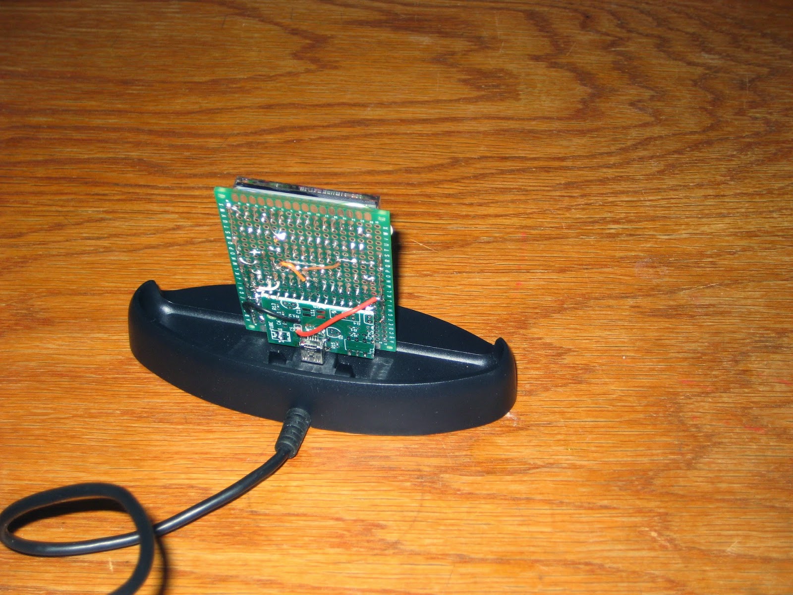
The easiest solution to "finish" the clock was to mount it on a phone dock charger I had around (which can be also found on ebay for $3 or so). Plugging the clock board into the dock's USB connector requires a "breakout" miniB (like this one sold by adafruit). I improvised one by cannibalizing a Geiger PCB, as shown in the photo below.


The "breakout" miniB connector is attached to the back of the clock board by soldering a few header pins in matching holes of the 2 boards. The assembly is mechanically solid.


The current draw at the lowest brightness (which is still very visible, as shown in the photo above) is between 20 and 40mA. At the highest brightness, the clock draws about 200mA.


Future improvements may include a Bluetooth module to display messages sent from a smart phone. And of course, designing a proper PCB :)

Update (Jul 20, 2014): A kit for this clock is now available.