Showing posts with label Wise Clock 3. Show all posts

Sunday, March 25, 2012

Troubleshooting guide for Wise Clock 3/4

This should really be a chapter of the assembling instructions for Wise Clock 3/4. Until I integrate everything into a single document, it is just another post that begged to be written (long ago, as a matter of fact).


1. Right after power up, the clock should make a beeping sound. If that does not happen, here are possible causes:
  • missing input 5V power; the optional power LED may be useful in this case, turned on when the power is present;
  • reset pin may be shorted to ground (the processor won't execute any code);
  • processor may not be powered: check that pin 10 has 5V and pin 11 is connected to ground;
  • faulty or missing the 16MHz clock for the processor; check crystal connections to the pins; if everything looks good electrically, try to upload a sketch; it that still doesn't work, test by replacing the processor or replacing the crystal;
  • buzzer may be disconnected; check connections between processor's pins and buzzer, shorts to the ground, terminal soldering.


2. The display does not light up at all (assuming the display is not defective):
  • faults in the connections to the display (right-hand header): look for shorts between neighbor pins in the display header; look for shorts between any signal pins in the display connector and ground;
  • output header (left-hand) display header may have shorts between neighbor pins or pins shorted to the ground;
  • the board's female connectors may be misaligned (shifted by one) when plugged in the display's male headers.


3. Getting SD card error in "Quote" mode:
  • faulty SD card; check the SD card itself by reading it in a PC; must be formatted FAT16 (therefore 2GB or smaller);
  • the required text files may be missing; check for their presence in the root directory;
  • SD card may not be powered; check 3V3 power on the third pin from the left (second pin from the left is connected to the ground);
  • check voltage divider resistors R5, R6, R7 (under the processor) and make sure they are 4K7.


4. Pressing a buttons (Set, Menu or Plus) does not trigger the expected action:
  • button itself may be defective, either always open (there is no contact between button's terminals when button is pressed) or always closed (short between terminals); verify with a multimeter that the button works correctly;
  • look for potential shorts between the "active" terminal (connected to the processor pins D0, D1 and D2/D3, see schematic) and ground.


5. Communication error when trying to upload a sketch:
  • make sure you plugged the FTDI cable/breakout the correct way/orientation, with the Ground/Black terminal to the right;
  • check the Rx/Tx connections to the processor (pins 14 and 15); make sure that they are not cut or shorted to the ground;
  • "stk500_getsync(): not in sync: resp=0x00 error" usually indicates that the upload speed is incorrect; for the ATmega644P processor, the upload speed must be 38400 (defined as atmega644.upload.speed=38400 in boards.txt); for the ATmega1284P processor, the upload speed is 57600;
  • if you get "avrdude: Yikes!  Invalid device signature. Double check connections and try again, or use -F to override this check", temporarily modify the signature in file hardware/tools/avr/avr/etc/avrdude.conf with one of these (depending on your processor):
    • signature = 0x1e 0x96 0x0a;   //  for ATmega644P
    • signature = 0x1e 0x97 0x05;   //  for ATmega1284P

Thursday, December 1, 2011

Wise Clock 3 - Dec 2011 software release

From the desk of Mr. Ruud, a new software release for Wise Clock 3 is now available.
Below is the long list of impressive features, improvements, changes etc. Ruud, thanks again.

  • Because of the large number (28) of menu entries the menu is now split in 2 loops, one for the Apps and one for the Settings.
------------------
  Apps menu loop:
  SETUP, QUOTE, BIG, TIX, WORDS, CNTDN, STOPW, SCORE, PONG, PACMN, TCLOK, UTC, LIFE, DEMO, STATS.

  Settings menu loop:
  APPS, ALARM, AL+/AL-, DATE+/DATE-, REMI+/REMI-, TEMP+/TEMP-, MESG+/MESG-, CHME+/CHME-, FONT+/FONT-, CELC/FAHR, 24H+/24H-, TIME, Y M D, DAY, SLEEP.

Selecting the "SETUP" menu entry will take you to the Settings menu loop, selecting the "APPS" menu entry
will take you to the Apps menu loop.
------------------
  • Stopwatch: This will show the time passed by in tenths of seconds, pressing the Set key will show the "lap" time.
  • Count Down Timer: This timer allows for setting a time of up to 24 hours and will beep 3 times after counting down to 0 seconds.
  • TIX clock: Showing the time using colored squares (if you do not know what a TIX clock is, Google it!) The PLUS key alows for changing the interval between 1, 4 and 60 seconds.
  • Time Clock: This allows for recording the amount of time spent on a project. You clock "IN" at the start of the project and clock "OUT" when you are finished for the day. The Time clock will show the total amount of hours and minutes spent on that project over several days. It allows for 5 different projects. A project may be cleared by pressing the Plus key when the "IN?" text is displayed, a future version will store all "IN" and "OUT" times together with the project number in  an Excel compatible file on the SD card. This file may then be processed on a PC using Excel.
  • "Word Clock": This will show the time and date using words instead of numbers. All "words" come from a "word" text file on the SD card and can be changed with any editor. At runtime you may choose from 10 different "word" files. Currently there are 5 different "word" files included:
  1. word1.txt The "official" English version showing: "The time is seven minutes past one o'clock in the morning on Monday the fourth of July."
  2. word2.txt The short English version showing: "It's one oh-seven am"
  3. word3.txt The "funny" English version showing: "It's 5 + 2 past six and you are up early"
  4. word4.txt The French texts version showing: "Le temps est sept minutes apres une heure du matin."
  5. word5.txt Example file for advertisement purposes, showing texts like: "We are now closed, opening hours are from 9 - 5" or "10% extra discount from 12 - 1".
  You may create your own versions with whatever texts/language you like, see the word1.txt file for details.

  • New large Font: This new proportional font, selected by "FONT+/FONT-", is 14 dots high and has variable width (letter i = 2 dots wide, letter m = 10 dots wide).
  • The "message.txt" file now contains, 10 different personal messages, the "MESG+" menu entry allows for selecting one of them (M1, M2, M3 etc.).
  • The "Quotes" menu entry now let you choose from up to 10 different "Quotes" files named quot1.txt, quot2.txt etc. several sample files (like: Texts by Shakespeare, fake alarm system, Spanish lesson, the clock's user manual (what you are reading now = "quot0.txt") are included. If you select the 11th file then the "message.txt" file is displayed which shows e.g. all 10 personal messages, reminders, DST etc.You may put your own "quote" file on the SD card, make sure that lines are not longer then 175 characters and end with a Carriage Return and Linefeed character. The file must be bigger then 512 bytes.
  • It is now possible to put characters in the non visible "video" ram and make them visible by overlaying the present display in horizontal or vertical mode. When in Big Mode, press the Set Key to see a demo.
  • The "UTC" mode now allows for changing the number of hours difference (+12 till -12). It allows for showing the time in "Graph" (= analog clock) or "Text" mode. The "Time.txt" file is no longer used and should be removed.
  • The temperature (TEMP+ menu entry) will now also show the highest and lowest temperature for that day.
  • The brightness is now changed with the Plus Key and the scroll speed with the Set key. The Set key is used in some of the new apps, but the brightness can always be changed with the Plus Key. 
  • "STATS" menu: This menu entry will show the highest and lowest temperature for the current year, the last time the power went off and the time when the power came back. It may take up to 24 hours before this info is available.

NOTE: The filemanager for the SD card is limited, so if you want to make any change to the files on the SD card then format the SD card first and copy all files in one go to the SD card. Also there cannot be more then 16 files on the SD Card.


Friday, November 18, 2011

"Make: Special Issue: Ultimate Kit Guide" featuring Wise Clock 3

Thank you for the honor, Make: magazine!


Here is the actual Make: web site dedicated to kit reviews.


Tuesday, September 20, 2011

Wise Clock 3 with Duino644

Let's start with a bit of "history".
Duino644 was designed to match with (plug into) the now-discontinued 2416 mono-color LED display from Sure Electronics.
Wise Clock 3 board was designed to plug into the 3216 bi-color LED display from Sure.
Both boards have a similar schematic, based on ATmega644, and they share similar features: RTC (DS3231) on I2C, SD card, piezo buzzer, 3 user buttons.

There are a few differences between the 2 boards:
  • Duino644 has IR receiver, connected on D2, whereas Wise Clock 3 has the Plus button on D2 and no IR receiver;
  • Wise Clock 3 has D11 connected to pin 2 (CLK) of the 3216 display; on Duino644, since the 2416 display does not require an input on pin 2, D11 is not connected.

Our goal is to adapt the "old" Duino644 board to the 3216 bi-color LED display and run the Wise Clock 3 software on it. This is easily achieved by doing the following hardware hacks:
1. connect the processor's pin 17 to pin 2 of the display's connector (red wire in the photo);
2. solder a bridge between processor's pins 3 and 4 (also visible in the photo);
3. cut out the IR receiver.


Now upload the Wise Clock 3 sketch (download latest version from here).
Plug the Duino644 board into the 5mm display, as shown in the photo above, then power it with the USB miniB cable. Surprisingly, the ensemble looks pretty functional and practical as it is: the buttons are accessible at the top (albeit a bit deep), the board is flush with the display, and the power (USB) socket is on the right side.
The enclosure could be a similar pair of plexiglass plates as used in Wise Clock 3. This bigger Wise Clock 3 would be more suitable to be hang on a wall (rather than sit on a desk).

Note that the Duino644 I tested uses DS3231. A version with DS1307 should work the same (except it will show 0 as the current temperature, I think).

As always, feedback is appreciated.

Sunday, September 18, 2011

Wise Clock 3 with 5mm LED display

I recently bought the 5mm LED display from Sure Electronics (same datasheet as the 3mm LED display), just to see how it would work with the Wise Clock 3 board (so I can answer the questions related to this combination).

As expected, just plug the Wise Clock 3 board into the "INPUT" connector of the display (as shown in the photo below), and everything should work. Since you may not want the board to stick out, a better solution would be to connect the two using the ribbon cable provided with the display (you would need to replace the 2x8-pin female header with a a 2x8-pin male header on the Wise Clock 3 board though).


Update (Jul 20, 2014): Photos on how to connect the Wise Clock 4 board to the 5mm display using the ribbon cable can be found here.

This is a huge display. I think it may be visible from 30 meters away (can you imagine Wise Clock 3 in a public plaza?!).


Save on other technologies by using Lenovo coupons.


Related posts:

Tuesday, September 13, 2011

Night and Day add-on kit

Want to build the Night and Day clock as shown by Justin?


Here is how we can help (and this is the exact reason why we described Wise Clock 3 as "highly hackable"):

1.  If you already have Wise Clock 3, buy just the "Night and Day add-on kit", which includes
  • the world map printed on thick velum paper;
  • one thin (1.5mm) transparent acrylic laser-cut plate;
You will need to upload the Night and Day sketch yourself (read about the process here).


  (US$10, free shipping to North America)


  (US$12, free shipping anywhere in the world)


2.  If you don't have Wise Clock 3 already, you can order the "Night and day add-on kit" alongside either the board kit or the complete kit. In this case, we will upload the sketch onto the processor for you.

Tuesday, August 23, 2011

Wise Clock 3 User manual

Update Mar 24, 2011
New features have been added in the Dec 2011 release, see this post.


I was finally able to put together a brief "user manual" for Wise Clock 3, which is also the last step of my "Wise Clock 3" instructable.

Here it is, below, cut and pasted from the instructable.

Wise Clock 3 has 3 buttons, named (in the silkscreen on the board) "Menu", "Set" and "Plus". The "Menu" button is the rightmost one as you face the clock, "Set" is the middle button.

By pressing the "Menu" button, the menu options are shown at the top of the screen, in sequence. A menu option is selected by pressing the "Set" button. Some of the menu options (e.g. "Time", "Date") allow the user to set values, for example the time, the date etc. To increment these values, the user presses button "Plus".


1. Set up the time
 - press "Menu" repeatedly until the option "TIME" is shown;
 - press "Set": now, one of either hours or minutes will start blinking;
 - press "Plus" to increment the blinking value; for hours, next value after 23 is 0; for minutes, next value after 59 is 0;
 - to change between setting (blinking) hours and minutes, press "Set";
 - after the desired time is set (values for hours and minutes are on display), wait about 4 seconds for the blinking to end; this is the time now stored by the clock.
Note: The value for seconds is always set to 0 every time the value for hours or minutes is incremented.


2. Set up the date
 - press "Menu" repeatedly until the option "DATE" is shown;
 - press "Set": the top part of the display will show "Y M D", and the bottom part will show the date, in the format "YYMMDD" (year/month/day);
 - press "Plus" to increment the blinking value; for years, next value after 50 is 0; for months, next value after 12 is 1; for days, next value after 31 is 1;
 - to change between setting (blinking) year, month and day, press "Set";
 - after the desired date is set (values for year, month and day are on display), wait about 4 seconds for the blinking to end; this is the date now stored by the clock.


3. Set up the day-of-week
 - press "Menu" repeatedly until the option "DAY" is shown;
 - press "Set": now the bottom half of the display will show the first three letters of the day of the week (e.g. Mon, Tue etc);
 - press "Plus" to increment the day;
 - after the desired day is reached (shown on display), wait about 4 seconds and the "DAY" option will be exit automatically; this is the day now stored by the clock.


4. Set display brightness
Every time the "Set" button is pressed in one of the main display modes ("Quotes", "Pong", "Pacman", "Big"), the brightness of the LEDs increases one level (out of 5 levels); next after the highest brightness level is the lowest level.


5. Set quote scrolling speed
To increase the speed of the scrolling, press the "Plus" button when in the mode "Quote". There are 5 speeds. Next after the highest speed comes the slowest.


6. Display modes
Changing the display modes is done by pressing the "Menu" button, then selecting the mode shown by pressing the button "Set".
The main mode is "Quote", which displays scrolling quotations, read from SD card, on the half top of the screen.

Other modes are:
 - "Pacman" - Pacman passes by every minute;
 - "Pong" - as in the old-days tennis game console; hours and minutes are displayed on both sides of the net, at the top of the screen, and change when a player "loses", every minute, of course;
 - "Big" - hours, minutes and seconds are displayed on the whole screen, in may different fonts;
 - UTC (universal time), useful for radio amateurs;
 - "Score" - allows keeping the game's score between two players, between 0 and 99.


7. Clock settings (options)
 Beside the current time, Wise Clock 3 can also display:
 - current date, formatted as "Month Day, Year"; this setting is enabled/disabled through the "DT+"/"DT-" menu options.
- temperature, in both Celsius and Fahrenheit; this setting is enabled/disabled through the "TEMP+"/"TEMP-" menu options.
- a personalized, user-editable message, read from SD card (e.g. "Happy Birthday dear John"); this setting is enabled/disabled through the "MESG+"/"MESG-" menu options.
- reminders for special events (anniversaries, Christmas etc), also user-editable on SD card; this setting is enabled/disabled through the "REMI+"/"REMI-" menu options.
- hours as maximum 12 or 24; this setting is enabled/disabled through the "24H+"/"24H-" menu options;
- enable/disable chime (short beep at the bottom of the hour, double beep at the top of the hour), by selecting "CHME+"/"CHME-" respectively.

Note: Menu will no longer show entries which do not make sense, like "DATE+" when the Date is already on.


8. Set up the alarm time
Alarm time can set through the menu option "ALARM". Press "Menu" button until you reach this option, then press "Set". From here on, the process is the same as setting up the time (point 2 above).

When alarm time is set and the alarm is active/enabled, the hours and minutes are separated by a colon, e.g. 15:43. If the alarm is disabled, a dot is used to separate the two, e.g. 15.43.

Another alarm-related feature: 3 hours before the alarm goes off, the time is displayed in orange, 2 hours before the alarm goes off in red; otherwise, time is displayed in green.


9. Enable/disable the alarm
The alarm is activated (will sound) only if the alarm is enabled. Enable/disable the alarm by selecting the "AL+"/"AL-" menu option.

When the alarm goes off, the clock plays "Frere Jacques", followed by a siren. The alarm can be stopped (silenced) by pressing any button.


10. Displaying reminders
At startup and at midnight the "message.txt" file is scanned for any reminder for that new day. An orange dot is displayed at the bottom during this scan. If a reminder is found then it will be displayed, like the quotes, for the next 24 hours.
The message file may also contain the start and end date of the Daylight Saving Time period (DST), this will adjust the clock by 1 hour.
The personal Message is still contained in this message file but must now start with [M1] which will allow for more then 1 Personal Message in a future release.
See message.txt for more details and add your own reminders.


Sunday, June 26, 2011

June 2011 release of Wise Clock 3 software

Mr. Ruud van der P. graciously offered his skills and time to extend and improve the Wise Clock 3 software, for which I am grateful.
He also took the video below, showing some of the newly added features in action.


This June/2011 release of Wise Clock 3 software (download from here) includes these features and changes:
  • PacMan - this new menu entry will show PacMan every 60 seconds.
  • Brightness of the display can now be changed with the Set key.
  • Show seconds in some of the "BIG" modes.
  • Time color when alarm is set: 3 hours before the alarm goes off, the time is displayed in orange, 2 hours before the alarm goes off in red; otherwise, time is displayed in green.
  • Chime may be enabled, giving a short beep at the half hour and a double beep at the full hour.
  • Alarm sound - the alarm will now play "Frere Jacques" followed by a siren and can be stopped by any button.
  • Menu will no longer show entries which do not make sense, like DATE+ when the Date was already on.
  • Score - new menu entry to keep a score for 2 players from 0 - 99.
  • Colors are now used in the Life and Demo apps.
  • Temperature is now a bit more accurate (after warming up) and uses the degree symbol to display the temp both in Celsius and Fahrenheit. In order to quickly see if the temp is rising or falling it is displayed with 1 decimal.
  • Bug fix: the file manager for the memory card did not read the last sector of a file and did not always handle the EOF (03) character correctly. It is important that all files have a EOF (03) character at the end to prevent reading behind the end of the file.
  • Displaying reminders:
    • At startup and at midnight the message.txt file is scanned for any reminder for that new day.
    • An orange dot is displayed at the bottem during this scan
    • If a reminder is found then it will be displayed (like the quotes) for the next 24 hours
    • The message file may also contain the start and end date of the Daylight Saving Time period (DST), this will adjust the clock by 1 hour.
    • The personal Message is still contained in this message file but must now start with [M1] which will allow for more then 1 Personal Message in a future release.
    • See message.txt for more details and add your own reminders.

Related posts:

Monday, June 13, 2011

How to define bitmaps and fonts

This piece of knowledge is especially useful for understanding and hacking the Wise Clock 3 software, but can  be also applied to any software that deals with pixel manipulation.

To define a small bitmap, start from a grid/matrix on paper (see photo below). Each square of the matrix will represent a pixel. Blacken the squares until the matrix resembles your bitmap. Next step is to translate the content of the matrix to numbers.


Let's take a closer look at the example below, a bitmap of 5x5 pixels.


This translates into an array of 5 numbers, one number per line. Each number is calculated by adding the values (at the top) of the selected columns.
So, the number for the first line is 14 (2 + 4 + 8), second number is 21 (1 + 4 + 16) and so on.
For the binary oriented fellows :), the hex values are between brackets.

Let's now jump to the actual code. The bitmap definition will look like this:


byte PROGMEM smallBitmap[3][5] = {
  {
    0x0E,    // _XXX_
    0x15,    // X_X_X
    0x1F,    // XXXXX
    0x1F,    // XXXXX
    0x15,    // X_X_X
  },
...
}


The above piece of code declares a two-dimensional ("[3][5]") array of bytes, in program space ("PROGMEM"). The first dimension ("3") represents the number of defined bitmaps. The second dimension ("5") represents the number of lines in each bitmap. A line in the bitmap definition is referenced using values for both dimensions. For example smallBitmap[0][4] is 0x15 and represents the last (index 4) line of the first (index 0) bitmap. [Note that array indexes start with 0, that is, first element in an array has index 0.]

Similarly, snippets of font definitions are shown below:


// define all ascii characters starting with 32 (blank);
unsigned char PROGMEM myfont[95][8] = {
  {
    0x00,    // ________   blank (ascii 32)
    0x00,    // ________
    0x00,    // ________
    0x00,    // ________
    0x00,    // ________
    0x00,    // ________
    0x00,    // ________
    0x00     // ________
  },
  {
    0x00,    // ________  !
    0x08,    // ____X___
    0x08,    // ____X___
    0x08,    // ____X___
    0x08,    // ____X___
    0x00,    // ________
    0x08,    // ____X___
    0x00,    // ________
  },
...
  {
    0x00,    // ________  0
    0x1C,    // ___XXX__
    0x26,    // __X__XX_
    0x26,    // __X__XX_
    0x26,    // __X__XX_
    0x26,    // __X__XX_
    0x1C,    // ___XXX__
    0x00,    // ________
  },
  {
    0x00,    // ________  1
    0x0C,    // ____XX__
    0x1C,    // ___XXX__
    0x0C,    // ____XX__
    0x0C,    // ____XX__
    0x0C,    // ____XX__
    0x1E,    // ___XXXX_
    0x00,    // ________
  },
  {
    0x00,    // ________  2
    0x1C,    // ___XXX__
    0x26,    // __X__XX_
    0x0C,    // ____XX__
    0x18,    // ___XX___
    0x30,    // __XX____
    0x3E,    // __XXXXX_
    0x00,    // ________
  },
  {
    0x00,    // ________  3
    0x3E,    // __XXXXX_
    0x06,    // _____XX_
    0x1C,    // ___XXX__
    0x06,    // _____XX_
    0x26,    // __X__XX_
    0x1C,    // ___XXX__
    0x00,    // ________
  },
...
}


The data structure "myfont" above is an array of 95 character-bitmaps, each bitmap having 8 lines and 6 columns.

Bigger bitmaps, those having more than 8 columns, require more than a byte for each line.
Take a look at the definition of the Pacman bitmaps below.


uint16_t PROGMEM bitmap[7][14] = {
  {
    0x02E0,    // ____XXXXX_____
    0x0FF8,    // __XXXXXXXXX___
    0x07FC,    // ___XXXXXXXXX__
    0x03FC,    // ____XXXXXXXX__
    0x01FE,    // _____XXXXXXXX_
    0x00FE,    // ______XXXXXXX_
    0x007E,    // _______XXXXXX_
    0x007E,    // _______XXXXXX_
    0x00FE,    // ______XXXXXXX_
    0x01FE,    // _____XXXXXXXX_
    0x03FC,    // ____XXXXXXXX__
    0x07FC,    // ___XXXXXXXXX__
    0x0FF8,    // __XXXXXXXXX___
    0x02E0,    // ___XXXXX______
  },
  {
    0x03E0,    // ____XXXXX_____
    0x0FF8,    // __XXXXXXXXX___
    0x1FFC,    // _XXXXXXXXXXX__
    0x1FFC,    // _XXXXXXXXXXX__
    0x07FE,    // ___XXXXXXXXXX_
    0x01FE,    // _____XXXXXXXX_
    0x007E,    // _______XXXXXX_
    0x007E,    // _______XXXXXX_
    0x01FE,    // _____XXXXXXXX_
    0x07FE,    // ___XXXXXXXXXX_
    0x1FFC,    // _XXXXXXXXXXX__
    0x1FFC,    // _XXXXXXXXXXX__
    0x0FF8,    // __XXXXXXXXX___
    0x03E0,    // ____XXXXX_____
  },
  {
    0x03E0,    // ____XXXXX_____
    0x0FF8,    // __XXXXXXXXX___
    0x1FFC,    // _XXXXXXXXXXX__
    0x1FFC,    // _XXXXXXXXXXX__
    0x3FFE,    // XXXXXXXXXXXXX_
    0x07FE,    // ___XXXXXXXXXX_
    0x00FE,    // ______XXXXXXX_
    0x00FE,    // ______XXXXXXX_
    0x07FE,    // ___XXXXXXXXXX_
    0x3FFE,    // XXXXXXXXXXXXX_
    0x1FFC,    // _XXXXXXXXXXX__
    0x1FFC,    // _XXXXXXXXXXX__
    0x0FF8,    // __XXXXXXXXX___
    0x03E0,    // ____XXXXX_____
  },
  {
    0x03E0,    // ____XXXXX_____
    0x0FF8,    // __XXXXXXXXX___
    0x1FFC,    // _XXXXXXXXXXX__
    0x1FFC,    // _XXXXXXXXXXX__
    0x3FFE,    // XXXXXXXXXXXXX_
    0x3FFE,    // XXXXXXXXXXXXX_
    0x3FFE,    // XXXXXXXXXXXXX_
    0x3FFE,    // XXXXXXXXXXXXX_
    0x3FFE,    // XXXXXXXXXXXXX_
    0x3FFE,    // XXXXXXXXXXXXX_
    0x1FFC,    // _XXXXXXXXXXX__
    0x1FFC,    // _XXXXXXXXXXX__
    0x0FF8,    // __XXXXXXXXX___
    0x03E0,    // ____XXXXX_____
  },
...
};

And this is the function that uses the actual Pacman bitmaps defined above.

/************************
 * load and display a given bitmap (defined in bitmaps.h);
 */
void putBitmap(int x, int y, byte nBmp, byte color)
{
  for (byte row=0; row < 14; row++)
  {
    uint16_t rowDots = pgm_read_word_near(&bitmap[nBmp][row]);
    for (byte col=0; col<14; col++)
    {
      if (rowDots & (1<<(13-col)))
        ht1632_plot(x+col, y+row, color);
      else
        ht1632_plot(x+col, y+row, BLACK);
    }
}

Now you should be all set to start your own animation (which is just a sequence of bitmaps).


Saturday, June 11, 2011

Pacman mode on Wise Clock 3

This display mode shows the time with seconds. To add some spice, Pacman passes by once a minute, when the minutes are about to change.


The animation is based on a short sequence of bitmaps (only monochrome at the moment) loaded from program memory.


The latest code will be released soon, and will include new features courtesy of fellow Arduino-er Ruud. Stay tuned.


Related posts:

Monday, May 23, 2011

World "day and night" on Wise Clock 3

Can you believe this? Wise Clock 3 displaying day and night world map, courtesy of Justin!


The map is printed on thick velum and sandwiched between the display (with a little space) and the front plate. The result looks really amazing.

Note that the "day and night" feature is also found on ClockTHREE (and maybe soon on C3Jr as well).

Saturday, April 23, 2011

Scrolling message sign display with Wise Clock 3

A feature of Wise Clock 3 board that was not previously "advertised" is its ability to drive more than one 3216 LED display, making it easy for anyone to quickly assemble a window sign display.

Wise Clock 3 board plugs into both connectors of the display. To cascade a second display, you will need to solder, on the Wise Clock 3 board, a right-angle 16-pin (8x2) male header in the place provided below the existing connector, then use the 16-wire ribbon cable coming with the 3216 display to connect this newly added header to the input connector of the second 3216 display, as shown in the photo below.


A demo (put together by Tim Gilmore) of a 64x16 windows sign display powered by Wise Clock 3 is shown in action in the following video. The demo software can be downloaded from here (for more details see this thread in the arduino forum).


Besides saving more, making your own clock brings a great sense of accomplishment.


Related posts:

Monday, March 21, 2011

Complete "Wise Clock 3" kit now available

The "Complete Wise Clock 3 kit", shown in the photo below, includes:


The main clock mode, "Quote" (hence the name "Wise Clock"), is shown in the video below.


Here is Wise Clock 3 running Pong as another clock mode:


Besides being an alarm clock, Wise Clock 3 has the following features:
  • ability to set the time, date and day from the buttons, in an intuitive and user-friendly way;
  • display a user-editable, personalized message (e.g. Happy Birthday John);
  • display the current date and the current temperature.
The software is published (open source) and available for anyone to modify and improve.


The hardware is compatible with Arduino IDE, and more accurately, is a clone of the Sanguino platform, using the same microcontroller (ATmega644P) and Arduino files.


  (US$120, free regular shipping to North America)


Related posts:

Thursday, February 24, 2011

Uploading sketches to Wise Clock 3/4

Update Apr 29, 2015
Here is another great tutorial on how to install the sanguino files, brought to you by the evilmadscientist team, the creators of Alpha Clock 5, another sanguino-compatible device.
It also seems that sanguino.cc was "upcycled" into something more revenue-producing.

Updated April 7, 2013 - added details (sanguino section in boards.txt etc).
Although this post was written for Arduino 21, it applies almost identically to Arduino 1.0 and later.
I say "almost" because:
  • file WProgram.h was replaced by Arduino.h
  • the original sanguino files may not be maintained publicly anymore. Instead of copying them from sanguino.cc, as suggested originally, you can download my updated (for Arduino 1.0+) version from here.
-------------------------------

Sooner or later, if you have Wise Clock 3 or 4, you may want to upgrade the software.
This process requires the following prerequisites:
  1. the Sanguino-related files need to be installed (since Wise Clock 3/4 is compatible with Sanguino);
  2. an FTDI cable/breakout is required to upload the sketch to the board.

To install the Sanguino files, you may follow the instructions found here. Basically, you need to do two things:
  • Firstly, add the definition of the Sanguino board to the file arduino21/hardware/arduino/boards.txt;
This "Sanguino" section should look like this:

sanguino.name=Sanguino
sanguino.upload.protocol=stk500
sanguino.upload.maximum_size=63488
sanguino.upload.speed=38400
sanguino.bootloader.low_fuses=0xFF
sanguino.bootloader.high_fuses=0xDC
sanguino.bootloader.extended_fuses=0xFD
sanguino.bootloader.path=atmega644p
sanguino.bootloader.file=ATmegaBOOT_644P.hex
sanguino.bootloader.unlock_bits=0x3F
sanguino.bootloader.lock_bits=0x0F
sanguino.build.mcu=atmega644p
sanguino.build.f_cpu=16000000L
sanguino.build.core=sanguino
sanguino.verbose=false

Pay attention to the upload speed (38400), which is "burned" in the bootloader and essentially important for communication with the board (sketch upload, serial monitoring). Also pay attention to the second last value, which indicates the folder where core files are found. This parameter MUST not be "arduino", but "sanguino". Thanks to Dave, who found this potential issue. Even though compilation and uploading were successful, the sketch failed to run as expected. This was because the core files used at build time were not those  for ATmega644/ATmega1284 (as used in sanguino).

If your processor is ATmega1284, the "Sanguino" section in boards.txt should look like this:

atmega1284.name=Sanguino W/ ATmega1284p 16mhz
atmega1284.upload.protocol=stk500v1
atmega1284.upload.maximum_size=129024
atmega1284.upload.speed=57600
atmega1284.bootloader.low_fuses=0xFF
atmega1284.bootloader.high_fuses=0x98
atmega1284.bootloader.extended_fuses=0xFD
atmega1284.bootloader.path=atmega
atmega1284.bootloader.file=atmega1284p_16MHz.hex
atmega1284.bootloader.unlock_bits=0x3F
atmega1284.bootloader.lock_bits=0x0F
atmega1284.build.mcu=atmega1284p
atmega1284.build.f_cpu=16000000L
atmega1284.build.core=sanguino

Note that for ATmega1284 the upload speed is 57600. Also note that the core folder (last parameter in the list above) is still "sanguino".

  • Secondly, create the folder "sanguino" and copy the Sanguino files, as shown in the screenshot below.


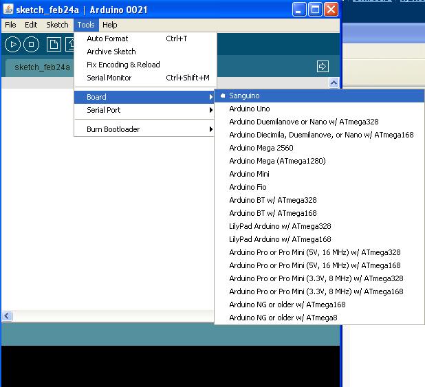
After these two steps are completed, you should see "Sanguino" listed in the menu "Tools/Board" of Arduino IDE 21 (used as an example here).


To upload the sketch, you will need to connect the board to the PC/Mac with an FTDI cable/breakout. The USB end of this cable gets plugged into the PC/Mac, the FTDI end gets connected to the Wise Clock 3/4 board as shown in the photo below.


With both the software and hardware in place, the upgrade will consist in the following steps:
  • download the latest software on the PC;
  • launch Arduino IDE and load the sketch;
  • compile, after chosing "Sanguino" as the target board;
  • upload to the Wise Clock 3/4 board.
Unziping the WiseClock3/4 source code (found here) should result in a directory structure as shown in the screenshot below.


If you get compilation errors related to "tone.cpp" file, like the following,

...\ArduinoIDE\libraries\WiseClock3\Sound.cpp: In function 'void soundAlarm()':
...\ArduinoIDE\libraries\WiseClock3\Sound.cpp:60: error: 'tone' was not declared in this scope
...\ArduinoIDE\libraries\WiseClock3\Sound.cpp: In function 'void beep()':
...\ArduinoIDE\libraries\WiseClock3\Sound.cpp:75: error: 'tone' was not declared in this scope

make sure the file Tone.cpp is present in the sanguino folder, as shown in the next screenshot.


(April 7, 2013: The following info is obsolete now. File WProgram.h was replaced by Arduino.h.)

Also, make sure that WProgram.h (in the sanguino folder) contains the line

void tone(uint8_t _pin, unsigned int frequency, unsigned long duration = 0);


Tuesday, February 8, 2011

Assembling Wise Clock 3/4 kit

Updated Dec 16, 2012
StefanK from Germany put together this a nice assembly guide for Wise Clock 4. Thanks Stefan!

Updated March 25, 2012
Here is a troubleshooting guide.

Updated March 10, 2012
Follow these same instructions to assemble Wise Clock 4 as well.
There are a few minor differences:
  • the optional power LED and resistor (both SMD) are not included; so skip step 2;
  • there are 2 extra resistors (R17 and R18), both 10k, on the right side of the processor;
  • the 470uF electrolytic capacitor (C4) must be placed with the minus terminal (marked with a band) towards the bottom of the board (this capacitor is useful only if an XBee/WiFi radio module is present);
  • the reset button is not used anymore;
  • the voltage regulator (78L33, through hole) was replaced with MIC5219 SMD, which is already soldered on the board.


Updated May 16, 2011
Thanks Scott for contributing this PDF version of the assembling instructions.

The Wise Clock 3 PCB comes with the SD card socket and the RTC chip already soldered, and looking like this.


Follow these steps:

1. Place and solder the miniB USB connector; actually, since this connector is only used for power, only the two extreme pins (1 and 5) must be soldered; the middle three can be left untouched. Make sure the connector is solidly anchored to the board through the 4 lateral holding pads; there will be lots of mechanical tension when the power cable is plugged/unplugged.


2. Solder the 100 ohm resistor (brown black brown), indicated on the PCB as R14, then the LED, paying attention to its orientation. The shorter pin, the cathode, goes into the left (as you look at the PCB as in the image below) hole. At this point, by plugging in the power cable, the LED should light up.


3. Solder resistors R5, R6, and R7, all 4K7 (yellow purple black brown brown), as shown in the next photo.


4. Solder the rest of the resistors, all 10K, as shown in the photo below.

Note that there are 9 resistors of 10K value (brown black orange): R1, R2, R3, R4, R9, R10, R11, R12, R13.


5. Solder the 40-pin socket, then the battery holder and the 4 buttons, see photo below.


6. Solder the 3 decoupling capacitors (100nF, labeled "104"): C3, C5, C8. Then continue with soldering the two smaller ones C1, C2 (both 22pF).


7. Insert the crystal (the small, metallic, oval cylinder, with 2 pins, labelled "16.000" on its top) in its position on the left side of the microcontroller socket, indicated by an oval (see the above image). Orientation is not important for the crystal.
Then insert the 3V3 voltage regulator (black, 3-pinned, semi-cylindric part labeled "L78L33ACZ") as indicated on the silkscreen by the half-cylinder on the right side of the microcontroller socket (its orientation is very important), then solder in place.
Next solder the 6-pin male header, and then the piezoelectric buzzer (its orientation is not important).
Look at the photo of the final assembled board (two photos down) before soldering, to make sure you have these parts placed correctly.

8. Insert the two 16-pin female headers on the back of the board (opposite to the parts side) and solder them on the top (parts) side.

To get the best alignment possible on these headers, Justin (thanks) suggested to insert the 16-pin headers into their sockets (in the display), then solder the board on top. (This is similar to the way the male headers are soldered on an Arduino-shield.)


9. It is time to add now the preprogrammed ATmega644P microcontroller. Before inserting it in the socket, slightly bend both sets of its pins on a table, so that they become parallel. Position the chip carefully on top of the socket, paying attention to its orientation: pin 1, marked with an arrow (triangle), must be close to the upper side of the board. Push the chip firmly into the socket.
Next insert the coin battery in the battery holder.
The assembled board should look like in the photo below.


10. Plug the Wise Clock 3 board into the 3216 LED display from Sure Electronics (not supplied in the Wise Clock 3 kit).


11. Copy the files (provided in the zip) onto the SD card, formatted FAT16, then insert the SD card in the socket.

12. Power the board with a miniB USB cable. You made it! Congratulations! Next, set up the clock (date and time) from the buttons. Then chose your favorite clock mode and enjoy.


Related posts:

Saturday, February 5, 2011

Wise Clock 3 kit now available in store

Updated Oct 21, 2011
This "Wise Clock 3 kit" does not include the display. To build the clock, you need to provide your own 3mm 3216 display (about $30 on ebay) and make your own enclosure.
"Wise Clock 3 complete kit", which includes the 3mm display and the laser-cut enclosure, is offered for sale here.

Now that I have a version of the software working well with Wise Clock 3 board, I can offer a "Wise Clock 3 kit" for sale. This board is designed to plug directly into the 3mm 3216 LED display from Sure Electronics. The software is pre-loaded onto the microcontroller chip.

Note: Wise Clock 3 board can be connected to the 5mm 3216 display only through the ribbon cable that comes with the display. If you insist on using the 5mm display (which I do not recommend), you will need to replace the right (looking at the top/component side) connector with your own 2x8 male header.


  (US$62, free shipping to North America)


This is, in summary, what Wise Clock 3 can do (Edit: the software is upgraded periodically, here is the latest):
  • display the current time, retrieved from the highly accurate real time clock that is DS3231;
  • along with the time, display quotations retrieved from a user-editable file on SD card;
  • display a personalized, user-editable, message, e.g. "Happy birthday John", "Happy Valentine's Day my dear love";
  • display the date and temperature;
  • display the time as a Pong Clock;
  • sound alarm at the specified, user-settable (through buttons), time;
  • set the time, date and day of week from buttons;
  • enable/disable the display of personalized message, date, temperature.


The content of the Wise Clock 3 kit is shown in the above photo and includes the following parts:
  • PCB;
  • ATmega644P microcontroller with the Arduino bootloader, preprogrammed with the latest Wise Clock 3 software;
  • 40-pin socket for the microcontroller;
  • SD card socket (*);
  • DS3231 real-time clock (*);
  • 16MHz crystal;
  • CR1220 coin backup battery for RTC;
  • holder for the coin battery;
  • piezoelectric buzzer;
  • miniB USB connector;
  • 9 x 10K resistor;
  • 3 x 4K7 resistor;
  • 100 ohm resistor;
  • blue LED;
  • 4 right-angle micro push buttons;
  • 2 x 16-pin female headers (display connectors);
  • 6-pin right angle male header (FTDI connector);
  • 3V3 voltage regulator;
  • 3 x 100nF decoupling capacitors;
  • 2 x 22pF capacitors.
(*) I solder the SD card socket and DS3231 chip for you.


   (US$62, free shipping to North America)