Tuesday, April 14, 2020

Electronics kits for kids

Continuing on the topic of "Introduction to Practical Electronics" course, today we are going to look at some of the electronics (soldering) kits available and suitable for the purpose.

What makes a good beginner electronics kit?
  • easy through-hole soldering
  • includes a variety of components
  • reasonably priced (this is relative; what may be expensive for me may be cheap for you)
  • standalone and all-inclusive: does not require extra parts/components/modules sourced from third parties and does not require loading software;
  • interesting (as opposed to boring) functionality: flashes LEDs, displays something on a screen, makes some sounds etc.
  • relative simplicity of the circuit, so it can be easy to understand and debug if necessary
  • aesthetics of the board (shape, colour, component placement etc.)
  • preferably open source
  • powered by low voltage (battery, USB, power adapter)
  • digital electronics rather than analog (easier to debug, if necessary)
  • practical utility: use it for a utilitarian purpose rather than forget about it once built
  • expandability: can be either integrated as part of a bigger project, or its capabilities and functionality can be extended by adding modules or parts
  • provides extra learning (besides soldering) by displaying information: wave forms, frequencies, binary/hex number representation, musical notes, proverbs etc.
  • satisfaction guaranteed once assembled and working  :)
Here is a list, in no particular order, of beginner kits I found to match some of the above criteria.

1. Elenco AM Radio kit


2. Chinese Radio kits: A, B


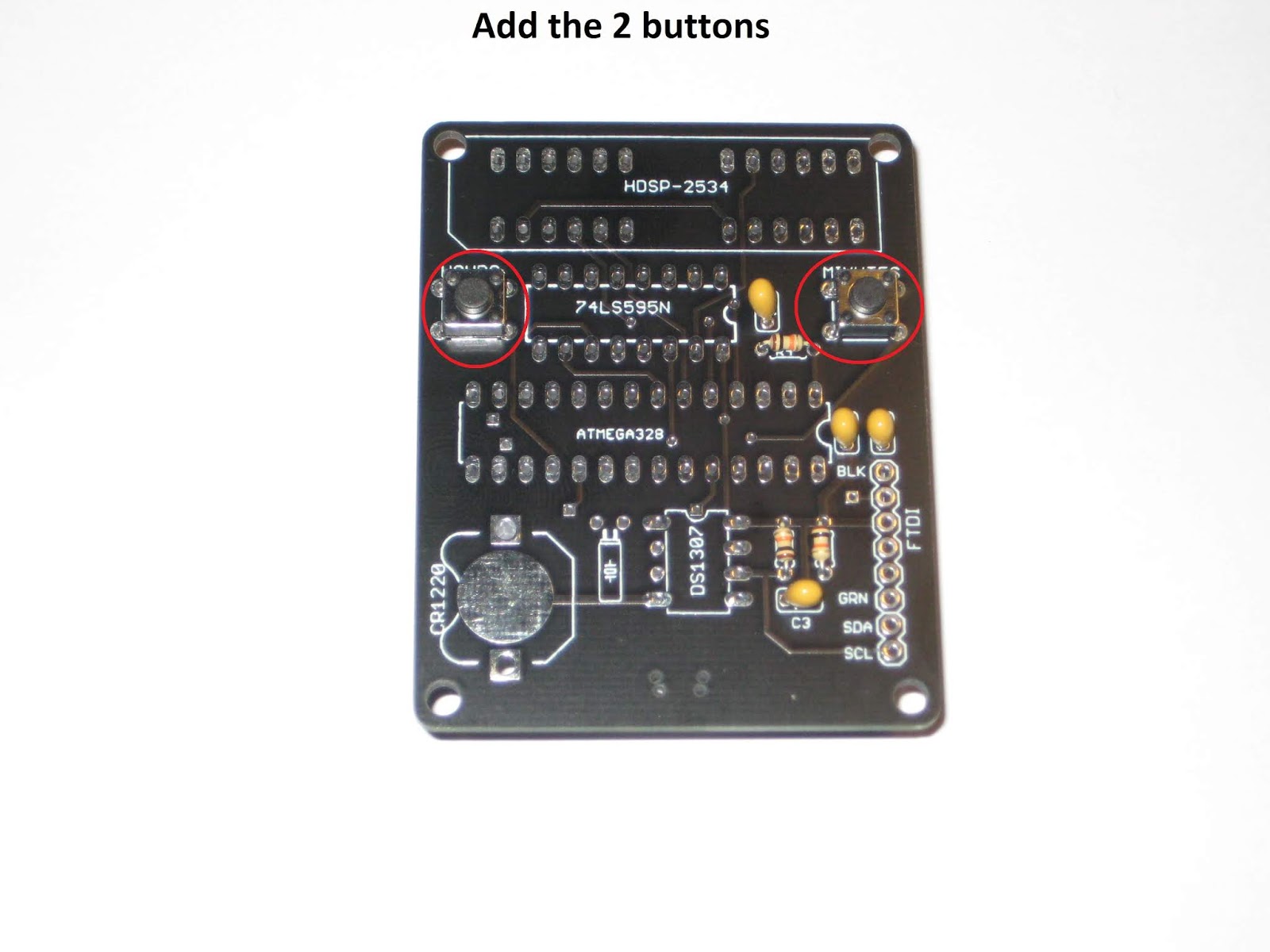
3. 6-digit LED Clock kit


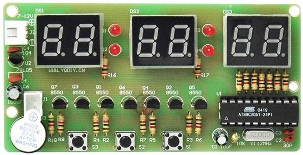
4. 4-digit LED Alarm Clock kit


5. 4-digit LED Talking Clock kit


6. Elenco two-tone European Siren kit


7. Retro Classic Game (Tetris, Snake etc.) kit


8. 3D Christmas Tree Flashing LEDs kit


9. Electronic Piano kit


10. Electronic 16 Sound Music Box kit


11. Astable Multi-vibrator Circuit Learn kit


12. Mini Speaker Box Amplifier kit


13. Aviation Band Radio Receiver kit


14. Calculator and Counter with LCD and Keyboard kit


15. "Three Fives" Discreet 555 Timer kit


16. TV-B-Gone kit


17. MintyBoost kit


18. MintySynth kit (now discontinued)


19. Drawdio kit


20. Electronic Hourglass LED kit


21. Round LED Clock kit


22. Signal Generator with XR2206 Adjustable Frequency kit


23. Solder:Time Desk Clock kit


24. Geiger Counter kit(s)


25. Wristwatch LED kit


26. Burglar Electronic Alarm kit


27. Conway's Game of Life kit


28. Music Synthesizer kit


29. Line Following Robot kit


30. Jameco Atari Punk Console kit


31. 555 Forrest Mims Project kit(s)


32. Tesla Coil kit


33. Velleman voice changer kit


34. Various badges (Maker, Day of Geek, Unicorn, and many many others)


Sunday, April 5, 2020

HDSP clock revision 2

The latest revision of the HDSP clock uses the same schematic, but offers an improved PCB layout, with:
  • 4 holes in the corners, for encasing;
  • addition of I2C signals to the FTDI connector, for expansion;
  • the regular push buttons can be replaced with 2-pin right angle buttons;

This revision was successfully used as the assembly kit in the "Introduction to Practical Electronics" course for Grade 6 students.

This would also be a good place for step-by-step assembly instructions, for those who require directions.


melt a bit of solder on the battery pad, to raise it (not pictured)


slide in the CR1220 battery, flat side (+ pole) up (not pictured)


Use a mini B USB cable to power the clock. It should work right away, since the processor is already programmed with the clock software. Use the "Hours" (left) and "Minutes" (right) buttons to set up the time.
Also, insert the CR1220 battery into the holder. It powers the DS1307 RTC (real time clock) when the clock board is disconnected from USB. Note that the small coin battery ONLY powers the RTC integrated circuit, and not the whole clock. The display is lit only when connected to the USB power.

Troubleshooting
  • check for missing soldering joints; you may have forgotten to solder some terminals;
  • check for solder bridges; solder blobs may accidentally connect adjacent holes/terminals that should not be connected;
  • make sure the orientation of the integrated circuits and the display matches the silkscreen, by checking the notches/indentations;
  • ensure that the ICs are fully and completely pushed in the socket, until their bottoms touch the socket's plastic;

What's next

1. Catch up on the theory:
  • recognize components symbols in schematics;
  • recap units of measure for some of the components (ohms for resistors, farads for capacitors); read their intended values (3 digits, color code), measure their real values using a multimeter;
  • understand electrical concepts: voltage, current, resistance (and their dependency), frequency; recap their units of measure;
2. Design and make an enclosure (hint: the easiest is to sandwich the board between plates of transparent acrylic, with standoffs in the 4 corners).

3. Look for a new kit to assemble.