Monday, February 17, 2014

"Method and apparatus" for mass-synchronizing clocks

Most of my clocks (e.g. this Nixie clock, this other Nixie clock, BookClock, and obviously Wise Clock 4) have on-board Bluetooth, intended mainly for setting up the time, without the need for buttons (the lousy holes I would drill may negatively impact the aesthetics).
To set up the time, simply send the command TIME=hh:mm:ss, where "hh", "mm", "ss" are the hours, the minutes and the seconds, respectively.

Setting up multiple clocks is a tedious process: pair your Android tablet with one at a time, then (from BlueTerm) send the command that includes the correct time. Then repeat for each clock.

What if you could broadcast the TIME=... command? And that command to include the most accurate time, acquired from GPS? This is what this post is about. Now you have the "method".

Next, to the "apparatus". It consists essentially of 3 parts: GPS receiver, microcontroller and Bluetooth master module. Putting them together is trivial, since both GPS receiver and Bluetooth module communicate through serial ports.


I used an old (now discontinued at the major online stores, but still available on ebay) Fastrax UP-501 GPS module I already had laying around. But any GPS receiver should work as well, including the Adafruit Ultimate GPS Breakout.

The "Bluetooth master module" is a re-programmed HC-05 (see the datasheet) as master, with CMODE=1 (for broadcasting).

The sketch, presented below, uses SoftwareSerial library to communicate with the GPS module (Rx on D3, Tx on D4) and TinyGPS library to extract the time from the NMEA sentence. The BTBee module is connected to the hardware serial port (D0, D1).


#include "TinyGPS.h"
#include "SoftwareSerial.h"
SoftwareSerial GPSSerial(4, 3);

// GPS Fatrax UP501, connected as follows:
// - power pin to 3.3V
// - ground pin to ground
// - VBAT pin to 3.3V if no battery is used
// - TX pin to D4
// - RX pin to D3 through a voltage divider (2 resistors, 10k + 4k7)

#define _DEBUG_  true

// commands  for GPS module;
#define PMTK_SET_NMEA_UPDATE_1HZ  "$PMTK220,1000*1F"
#define PMTK_SET_NMEA_UPDATE_5HZ  "$PMTK220,200*2C"
#define PMTK_SET_NMEA_UPDATE_10HZ "$PMTK220,100*2F"

// turn on only the second sentence (GPRMC)
#define PMTK_SET_NMEA_OUTPUT_RMCONLY "$PMTK314,0,1,0,0,0,0,0,0,0,0,0,0,0,0,0,0,0,0,0*29"
// turn on ALL THE DATA
#define PMTK_SET_NMEA_OUTPUT_ALLDATA "$PMTK314,1,1,1,1,1,1,0,0,0,0,0,0,0,0,0,0,0,0,0*28"

// MTK command datasheet at http://www.hhhh.org/wiml/proj/nmeaxor.html

TinyGPS gps;

void setup()  
{
  // default baud rate for BTBee (on hardware serial);
  Serial.begin(9600);

  // default baud rate for UT501 (on software serial);
  GPSSerial.begin(9600);
  
  // turn on all the available data (for 9600 baud you'll want 1Hz rate);
  GPSSerial.println(PMTK_SET_NMEA_OUTPUT_ALLDATA);
  
  // set update rate to 1Hz
  GPSSerial.println(PMTK_SET_NMEA_UPDATE_1HZ);

#ifdef _DEBUG_
  Serial.println("ready for reading GPS...");
#endif
}

void loop()
{
  acquireTimeFromGPS();
  delay(5000);
}

void acquireTimeFromGPS()
{
  unsigned long age;
  int Year;
  byte Month, Day, Hour, Minute, Second, Hundredths;

  if (feedgps())
  {
#ifdef _DEBUG_
    Serial.println("GPS feed acquired...");
#endif
    gps.crack_datetime(&Year, &Month, &Day, &Hour, &Minute, &Second, &Hundredths, &age);
    char buf[20] = {0};
    sprintf(buf, "TIME=%02d:%02d:%02d", Hour, Minute, Second+1);
    Serial.println(buf);
  }
}

bool feedgps()
{
  while (GPSSerial.available())
  {
    char c = GPSSerial.read();
#ifdef _DEBUG_
    Serial.print(c);
#endif

    if (gps.encode(c))
      return true;
  }
  return false;
}

As protoboard I used the XBee Shield from seeedstudio because it had a socket for my BTBee (plus 3V3 regulator) and also ample space for processor and GPS. (It could even fit in a Altoids tin if  the GPS receiver is soldered directly to the board, without headers.)

Future improvements should include a couple of status LEDs, one to show that the data was being acquired from GPS, another to indicate that the "TIME" command was successfully built and broadcast. Similarly but more expensively, a small OLED screen could be used to display the activity.
On the software side, the time, which comes as UTC in the NMEA sentence, should be adjusted to the current time zone, probably based on the longitude.

Saturday, February 8, 2014

Altoids Geiger counter

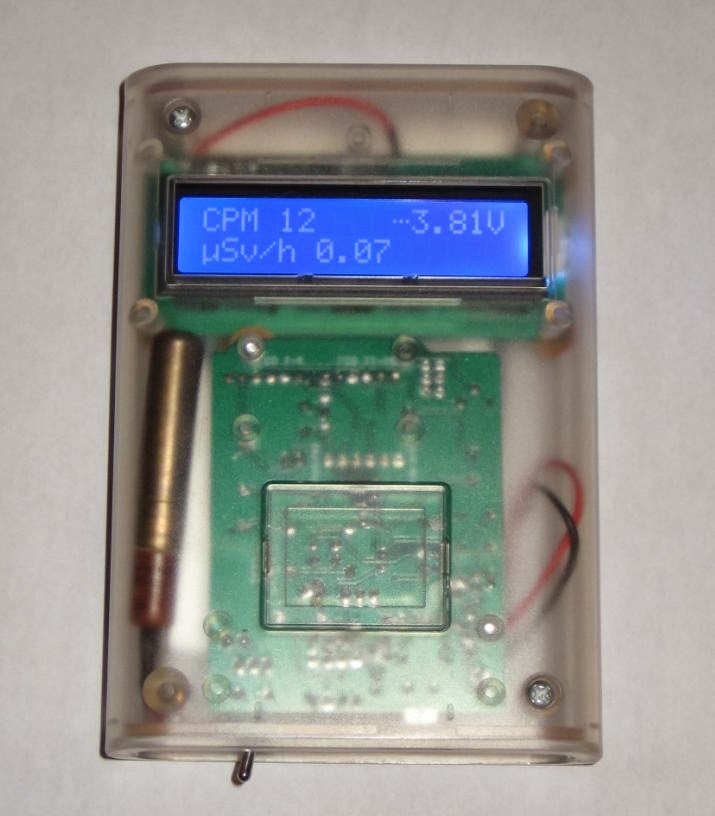
My "Remixed Geiger counter" board fits almost perfectly, by chance, in the "classic" Altoids box, with room left for the SI-29 GM tube, the 1100mAh LiPo battery and the 0.96" OLED display.


The ATmega328 processor runs at 8MHz with the internal oscillator, a better choice (than the 16MHz of Arduino 2009) for the LiPo voltage of approx 3.7V.  The display I used is compatible with the monochrome 128x64 OLED display from Adafruit.
It is powered at 3V3, requiring a voltage regulator (78L33, TO-92), placed where the the trim-pot (for adjusting LCD contract) was supposed to be (top-right corner of the board).

The sketch uses Adafruit_SSD1306 library, with the wiring to the display as defined below:

#define OLED_DC 8
#define OLED_CS 7
#define OLED_CLK 4
#define OLED_MOSI 3
#define OLED_RESET 5

Note that the same D3-D8 are used for connecting to the LCD 1602 display in the "regular" DIYGeigerKit.
Also note that I did not install the "click" LED nor the buzzer, relying instead on the OLED display to indicate the radiation level.

Since the lid needs to be open anyway in order to see the screen, I thought it does not make sense to drill 2 holes in the box for the USB miniB connector (used for charging the battery) and the on/off switch. (As well, this sounds like a believable excuse for being lazy.)


If I were to improve on it, I would replace the right-angle toggle switch with a straight-up one (easier to operate), then add a button or two for user inputs (configuration parameters, menu navigation etc). The "click" buzzer and the LED could be made "digital", wired to controller's outputs. Adding a Bluetooth module would be also useful (if it works at all from inside the closed box, I need to try it). Ideally, I would also add RTC, GPS and SD card, for logging purposes. And then it would become a smaller and cheaper version of Safecast bGeigieNano :)


Friday, January 31, 2014

Interrupt-based sketch for Adafruit coin acceptor

Some time ago I bought this coin acceptor. Programming it to accept 4 different types of coins is convoluted, but quite ingenious, and works exactly as the spec sheet indicates, without glitches. Surprising for such a complex task, considering that the user interface consists of 3 buttons and two 7-segment LED displays.
After setting it up, the mechanism identifies each coin type reliably, even providing user-friendly feedback (showing on the LED display the number of impulses sent over the COIN/white wire), very helpful for debugging.

Now onto actually using it. Adafruit's graciously provided the "Piggy bank" sample project,  including the Arduino sketch as well. The sketch however, counts the impulses simply in the loop() function. That may work fine in that particular setup, with just the coin acceptor (1 coin type nonetheless) and the LCD display. If you want to add more hardware (printer, buttons, bluetooth, SD card, LEDs etc), you need a smarter, hardware-independent, way to count the impulses from the coin acceptor. Naturally, that involves interrupts.

I present below a snapshot of my interrupt-based sketch, tested in a more complex hardware setup. The COIN wire is connected to D2, attached to interrupt INT0. Function coinISR() gets called for each impulse from the coin acceptor. A coin is recognized when a train of expected number of impulses is received in a sequence.


#define COIN_PIN 2

void setup()
{
  // Debugging output
  Serial.begin(9600);

  // set up the LCD's number of rows and columns:
  lcd.begin(16, 2);

  Serial.println("Ready...");
  
  pinMode(COIN_PIN, INPUT);
  attachInterrupt(0, coinISR, RISING);  // COIN wire connected to D2;
}


// total amount of money collected;
float money = 0.0;

// gets incremented by the ISR;
// gets reset when coin was recognized (after train of pulses ends);
volatile int pulses = 0;
volatile long timeLastPulse = 0;


// executed for every pulse;
void coinISR()
{
  pulses++;
  timeLastPulse = millis();
}


void loop()
{
  lcd.setCursor(0,0);
  lcd.print("Please put coins");
  lcd.setCursor(0,1);
  lcd.print("PAID $");
  lcd.print(money);

  long timeFromLastPulse = millis() - timeLastPulse;
  if (pulses > 0 && timeFromLastPulse > 200)
  {
    // sequence of pulses stopped; determine the coin type;
    if (pulses == 2)
    {
      Serial.println("Received dime (2 pulses)");
      money += .1;
    }
    else if (pulses == 5)
    {
      Serial.println("Received quarter (5 pulses)");
      money += .25;
    }
    else if (pulses == 10)
    {
      Serial.println("Received looney (10 pulses)");
      money += 1.0;
    }
    else if (pulses == 15)
    {
      Serial.println("Received tooney (15 pulses)");
      money += 2.0;
    }
    else
    {
      Serial.print("Unknown coin: ");
      Serial.print(pulses);
      Serial.println(" pulses");
    }

    pulses = 0;
  }
}


Wednesday, January 22, 2014

Geiger Counter remixed

One of the requirements I consider important when designing a device is the ability to repair it, in case it breaks down. This means that the device should be easy to dis-assemble into its components, ideally without using a soldering iron. To achieve this goal, I usually tend to use headers and sockets for connecting the boards between them. I also try to place the buttons/switches etc. directly on the board, eventually sticking out through holes in the panel, rather than using their panel-mount equivalents connected to the board with wires.

The main reason I called one of my latest device "ugly" in a recent post was because I could not meet this requirement (well, I did not design the whole thing either). Essentially, that particular Geiger counter is very difficult to fix. Accessing to the FTDI header to re-program the Arduino Mini is also challenging. If, for some reason, the LiPo charger breaks down, the replacement miniature board would require drilling, then trace-cutting, then some wires to be soldered to the traces. I would rather throw it away then go through the (still undocumented) exercise again.

Considering all of the above, I designed a Geiger counter board shaped and dimensioned as the original Arduino, so it can fit in the Arduino enclosure from Adafruit, together with the 16x2 LCD display. The schematic is based on BroHogan's DIYGeigerCounter, to which I added the LiPo charger (with USB miniB socket) and a toggle switch for power on/off.


It does not get much simpler than this. The Geiger counter board is screwed to the half case, together with the display. With the case closed, the "free-floating" Geiger tube and the LiPo battery are held in place pretty well without additional fasteners, just by being pressed against each other.


There are 2 LEDs soldered to the bottom side of the PCB: one indicates LiPo charging, the other is the radiation indicator. This being another reason the enclosure needs to be transparent or translucent (it's not only for showing off the simple yet elegant internals :).

The 3V3 LCD display is connected to the board with a pair of 6-wire ribbon cable which can be easily unplugged if necessary. Sketches are uploaded to the ATmega328 (SMD) through the 6-pin FTDI connector, from Arduino IDE (as a matter of fact, I uploaded the release 10.2 of the DIYGeigerCounter software by BroHogan).

There is enough room in the enclosure to fit a second SI-29 Geiger tube in parallel (electrically) with the existing one, for better sensitivity.
The counter works perfectly with the bigger SBM-20 tube as well, but it is a bit challenging to fit that inside without some compromises.

The bottom cover of the enclosure does not require any modification (e.g. filing, drilling); one opening is still used for the (now smaller) USB connector, the other (originally designed for the power jack) is re-purposed for the power toggle switch.


Note that the miniB USB connector is only used for charging the battery and not for uploading sketches or for USB serial communication.

It would be very nice if this stylish enclosure gets re-designed for the 128x64 OLED display.

Monday, January 13, 2014

Chumby Nixie clock

With my limited (read "non-existent") crafting resources (e.g. space, tools), the easiest way to enclose my Arduinix clock was by recycling my late Chumby's shell. Things almost magically fit together, with minimal thinking and work. I was able to cram inside the box a hand-wired Wiseduino with an Arduinix-remix shield and a 4-tube board.


The old Wiseduino would have come in handy if I had any left. I made one using the protoshield from Sparkfun, which also has a connector for the Bluetooth JY-MCU module. Beside the ATmega328, this pseudo-Wiseduino board includes a DS1307 with coin backup battery and a 7805 voltage regulator.

The tube board is attached with screws to an empty board that plugs in the Arduinix-remixed shield. (Note that one reason for "remixing" Arduinix was to re-arrange the parts sticking out, namely the mosfet and the capacitors, so that it allows another shield to be stacked on top.)


The clock has no user button (I glued the original snooze button on top, would have required extra work to re-use it), so the time is set through the bluetooth interface, similarly to my other Arduino Nixie clock.


The sketch (compiled with Arduino 1.0.4) is available here. Note that, unlike the original Arduinix sample sketch, the nixie-driving code is now using interrupts. This decouples the display logic from the clock functionality, also allowing for the addition of a buzzer alarm.