Friday, September 18, 2009

Buy Duino644 kit


Updated Sep 30, 2011 - DISCONTINUED
This kit is no longer offered. It was replaced by the Wise Clock 3 kit.


Updated Jan 27, 2011
A redesigned (revision 2.1) Duino644 is back in stock. Read more about it here.


Note: Although I added a few more components and I made the board a bit larger, I decided to keep the price unchanged. I hope this is appreciated :)
Also, the picture below won't accurately reflect the actual component set. Missing are the 4 right-angle push buttons (one is replacing the reset button), the micro-speaker and the high brightness blue LED.

I have a few Duino644 kits for sale, on hand and ready to ship. After they are gone, any order will be fulfilled in about 4 weeks time.
Duino644 kits are US$54, with free regular shipping to North America.

For only US$10 more, buy the 2416 LED matrix display from Sure Electronics (ebay), and you can have a nice gadget on your desk to impress your friends an colleagues.

The Duino644 kit includes the following parts:
  • PCB;
  • ATmega644 / 20MHz, with bootloader;
  • either 16 MHz resonator or crystal 16 MHz (plus 2 capacitors 22pF);
  • 40-pin socket for ATmega644;
  • SD card socket (SD card is not included);
  • DS1307 real time clock, either in DIP or SOIC package;
  • 24LC256 EEPROM, either in DIP or SOIC package;
  • 3V coin battery (CR1220 equivalent);
  • battery holder for CR1220;
  • crystal 32,768 Hz;
  • 2 x 16-pin (2x8) female headers;
  • 3 x capacitor 100nF;
  • 78L33 regulator (3V3);
  • 10 x resistor 10K;
  • 3 x resistor 4.7K;
  • micro push button (reset);
  • micro slide switch (power);
  • 6-pin angled male header (FTDI);
  • either USB miniB SMD connector or USB type B connector;
  • infrared receiver;
  • 40-pin female connector;
  • either molex 2-pin angled power connector or JST jack.


Assembling instructions are published here.

Related posts:

Introducing Duino644

Updated Sep 30, 2011 - DISCONTINUED
This kit is no longer available. A very similar kit is the Wise Clock 3.

A simple name from a simple mind: think Arduino clone powered by ATmega644.

Compatible with Arduino software environment (thanks to the Sanguino board, from which it was inspired), Duino644 offers more capabilities than a regular, ATmega328-based Arduino, in the same price range.

Duino644 was originally designed to be used in an advanced new version of Wise Clock. It features the same combo RTC + EEPROM as Wiseduino, and also an SD card socket and connectors for the 24x16 LED matrix display from Sure Electronics.

Duino644 can also be used as a general-purpose Sanguino-compatible board, having all ports (input/ouput pins) exposed and available for use.

Here are some of Duino644 features:

  • PDIP (40 pin) ATmega644 on socket, running at 16 MHz;
  • compatible with Arduino software environment through the addition of Sanguino libraries;
  • directly pluggable into the 2416 LED display from Sure Electronics;
  • semi-pluggable (just one of the two connectors) into the 0832 LED matrix display from Sure Electronics; display type (2416 or 0832) is selectable through jumper;
  • compatible with uzebox game console (requires a different crystal and the "uzebox shield" (under development));
  • relatively easy to solder, with mostly through hole components;
  • on board socket for either SD card or microSD card;
  • on board RTC (DS1307) in either PDIP or SOIC package;
  • on board EEPROM (24LC256) in either PDIP or SOIC package;
  • 6-pin FTDI connector with automatic reset capability;
  • powered, with regulated 5V only, through either standard 2-pin power connector (MLX-WF02R from molex or JST jack from seeedstudio) or USB (type B or miniB connector);
  • power on/off micro switch, easily accessible on the side;
  • available interrupt output pin from RTC;
  • on board backup battery (CR1220), allowing RTC to keep time even when Duino644 is not powered;
  • infrared receiver for remote control;
  • all 4 ports made available through extension headers, spaced at 0.1" multiples, for use with prototype boards;
  • ISCP6 connector for AVR programming.


A few Duino644 PCBs are shown in the photo below.


And this is an assembled Duino644, which is the base for Wise4Sure. With the current software, it works exactly like in this video.


Assembling instructions can be found here.


Creative Commons License
Duino644 by FlorinC is licensed under a Creative Commons Attribution-Share Alike 3.0 Unported License.


References:

Related posts:

Thursday, September 17, 2009

Assembling the "LED matrix shield" kit

Updated May 16, 2011
Fellow Arduino fan Scott graciously offered this PDF version of the assembling instructions.


Updated Feb 17/2010
The content of the "LED matrix shield" kit was slightly changed: the 40-pin female header used as socket for the LED matrix is now replaced with two 12-pin machined female headers, making a much better quality connector, suitable for the thin pins of the LED matrix.
Since these new headers are not as high, the IC sockets, if soldered, would impede on the complete insertion of the LED matrix in the headers; therefore, they have been dropped.

The LED matrix shield for Wise Clock kit includes the following components (also shown in the photo):


Like Wiseduino, the LED matrix shield kit requires some basic soldering skills.
One of the most important aspects of correctly assembling the kit is paying attention to the orientation of the ICs and the LED matrix. The ICs must be positioned to match their notches with those on the silkscreen. Pin 1 (and also Pin 13) of the LED matrix are clearly marked on the silkscreen. To eliminate any doubt I also hand-wrote the pin numbers on the back of the LED matrix.

Following are the steps for assembling the board:
  1. cut the male headers in 4 pieces (two 8 pins, two 6 pins) and solder them in their right places; the easiest way to perform the soldering is to insert the pins into the Arduino extension connectors, like you had a shield in place already;
  2. solder the two 12-pin headers;
  3. solder each 100 ohm resistor after placing it vertically (bend one terminal 180 degrees);
  4. place and solder the 2 push buttons;
  5. solder the remaining 2 resistors, R17 (10K) and R19 (100 ohms);
  6. solder the infrared receiver, then bend it 90 degrees so it becomes parallel to the board and also sticks out a bit;
  7. insert the 3 ICs, matching their notches with those on the silkscreen, then solder them (before inserting them, don't forget to bend their pins, as shown here);
  8. solder the 2 decoupling capacitors (100nF);
  9. carefully insert the LED matrix, paying attention to its orientation (the pin numbers are hand-written on the back, for easier identification).
In the end, the assembled LED matrix shield should look like this (shown plugged into Wiseduino):


The code for Wise Clock can be viewed and downloaded here.

Related posts:

Enclosures - part 3

Since my last posting on enclosures, I have found a few interesting ones that are worth mentioning.

This USB enclosure may qualify as one of the smallest. And here is an update, enclosing an actual circuit board.


Cases in different sizes, from Staples
This particular one (0.55L) fits perfectly the 8x32 LED matrix display from Sure Electronics.


A simple yet practical enclosure


The Chronulator
Not a mere enclosure, but rather a work of art. Check out lots of other Chronulator mods here.


Wednesday, September 16, 2009

Wise Clock sketch

In essence, what the Wise Clock sketch (download from here) does is to display, by scrolling from right to left, two pieces of information:
  • the current time, retrieved from a real time clock (RTC) and
  • a quotation (a one-liner piece of text) retrieved from an external EEPROM.

Some auxiliary functionality offered by the sketch:
  • allows user interaction through a Sony TV remote control and through the "Menu" push button (useful when testing or when the remote is not at hand);
  • displays selectable menu items;
  • sleep mode (turn display off);
  • time could be set through the remote control;
  • uses different colors for display.

Troubleshooting the Wiseduino board

One of the most common problem reported when building an Arduino-clone (not necessarily Wiseduino) is the failure to communicate with the board, that is, the sketch cannot be uploaded.

Here are a few things to check in this case.

- make sure the polarity is correct: the 5V and GND pins in the power connector are indicated in silkscreen;
- measure the current taken by the board; this would give an indication if there is a short somewhere; normally, when only the Wiseduino board is powered (no shields attached), the
consumption should not be higher than 30-50 mA, at most;
- the power switch must have the "lever" towards the female headers to power the board;
- the batteries must be rechargeables (1.2V each, making about 4.8V together); 4 regular AA (new) batteries would provide at least 6V, a bit too much for the ICs;
- make sure the FTDI cable is inserted correctly: ground (black wire) closer to the female headers;
- are the ICs properly inserted into their sockets (so that the notches match, see the photos for assembly instructions)?


A lot more explanations should be provided, no doubt. Your comments, observations, issues are welcome. Also, your contribution to the development and refinement of this code is appreciated.

Related posts:

Buy LED matrix shield kit - DISCONTINUED

Updated Sep 29, 2011
Check out the newest LED matrix shield here.


Updated Sep 1, 2011
As of today, this kit is no longer offered, since I ran out of LED matrices. If you are still interested in the PCBs (because you already have a compatible LED matrix, for example, or maybe you just want to adapt a similar one), drop me a line.


Updated Feb 16/2010
The 40-pin female header, meant as a socket for the LED matrix, was replaced with two 12-pin machined female headers (see this posting), a much better solution. In the same time, since these headers are shorter, the LED matrix will be closer to the board, touching on the ICs underneath. Therefore, I eliminated the 3 IC sockets, since they do not make sense anymore.
Also, the 220 ohms resistor was replaced with a 110 ohms.


Here you can order a kit of the LED matrix shield for Arduino.
Paired with Wiseduino, which has on board RTC (real time clock) DS1307 and EEPROM 24LC256, it makes the Wise Clock.
(Please check out The Shoppe for more kits.)


The LED matrix shield kit includes the following components:
  • PCB, black;
  • 8x8 bi-color (red + green) LED matrix, medium size (47 x 47 mm);
  • 2 x 74HC595 shift registers with 2 x 16 pin sockets;
  • ULN2803A with 18 pin socket;
  • 17 x 110 ohm resistor;
  • 2 x micro push button;
  • 220 ohm resistor;
  • 10K resistor;
  • 2 x 100nF capacitor;
  • 40 pin female header; 2 x 12-pin machined round female header;
  • 40 pin male header;
  • infrared receiver.


Schematic can be downloaded here (Eagle file).


Board layout (download Eagle file here)


Assembling instructions are here.


See related posts:

Tuesday, September 15, 2009

Finally! PCBs galore!

After a long and anxious wait, I finally got the PCBs for Wiseduino and the LED matrix shield.
All outstanding orders will be shipped today.
Thank you all for 3+ weeks of unbelievable patience.


All future orders will be mailed the same day.

Sunday, September 6, 2009

Assembling Duino644

This the schematic (download Eagle file) for Duino644 revision 1.1 (Oct/09)

and the board (download Eagle file):

If you bought the Duino644 kit, you received the following components:
  • PCB with the SD card socket soldered on it;
  • ATmega644 microcontroller and its 40-pin socket;
  • DS1307 real time controller, in either 8-pin DIP (with a socket) or SOIC (surface mounted) package;
  • 24LC256 EEPROM, in either 8-pin DIP (with a socket) or SOIC (surface mounted) package;
  • CR1220 (or equivalent) coin battery;
  • coin battery holder;
  • either a 16MHz crystal and 2 capacitors 22pF, or a 16MHz resonator;
  • crystal 32,768Hz for RTC;
  • 4 right angled push buttons;
  • micro-speaker;
  • high intensity blue LED (SMD, 1206 package);
  • USB miniB-type connector;
  • JSP 2-pin jack;
  • JST 2-pin power connector (with red-black cables soldered);
  • 2 female headers 2x8 pins;
  • 40-pin female header;
  • L78L33 voltage regulator (3V3);
  • infrared receiver IC;
  • 6-pin right angled male header (FTDI connector);
  • 3 decoupling 100nF capacitor;
  • 2x3 pin male header (ICSP connector);
  • 10 resistor 10K;
  • 3 resistor 4K7;
  • resistor 75R.
As with the other kits, soldering the components is not for absolut beginners: this should not be the first kit you assemble. The challenge comes from the few SMD components. Although these are the biggest SMD (surface mounted) packages you will find (SOIC for ICs, 1206 for LED, and the USB miniB), you would still need, depending on your experience, tweezers, de-soldering braid, flux pen.

So here is how we should proceed with the assembling.

1. Solder the USB miniB connector first. Place the connector with its bumps in its holes, so it fits in its place. Then solder the 4 outside extremities to the pads, so it becomes solidly attached to the board. Now solder the 5 pins, with disregard to the bridges that may occur. The next step should be to remove those bridges with the braid.

2. Solder the 75 ohm resistor in its place (R14). This is the current limiting resistor for the LED.

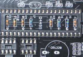
Note: The kit has 3 color-coded resistor values: 10K (brown, black, orange, gold), 4K7 (yellow, purple, black, brown, brown) and 75 ohm (purple, green, black, gold, brown). To simplify identification for those who don't want to consult the color-code chart, use the following photo.


3. Next, solder the SMD LED. The cathode of the LED is marked (green dot, visible through magnifying glass). The cathode is marked on the PCB as well, with 3 dots. Melt some solder on the cathode pad; place the LED's cathode over that pad and solder it; then solder the anode.

4. Time to check that the board gets power from USB, by plugging in the USB cable. The LED should become bright blue. We have ignition!

5. Perform this step if you have the SMD (surface mounted) version of the RTC and/or EEPROM. For best results, moist their pads with a flux pen before you solder them. Avoid using the "de-soldering braid" to remove the eventual bridges, since these are temperature sensitive, unlike the USB connector soldered earlier. (Pay attention to the orientation of these chips: the dots marking pin 1 must be closer to the bottom of the PCB.)

6. Solder the 4K7 resistors (yellow, purple, black, brown, brown), R5, R6 and R7. Then continue with the remaining resistors, all 10K.

7. Solder the IC sockets, for ATmega644, RTC and EEPROM (if the last two were provided). Pay attention to their orientation, so that their notches match the notch in the silkscreen (this is not vital, but it will help later to correctly place the ICs).

8. Solder the two crystals (16MHz and 32768Hz), then the capacitors (C1 and C2 are 22pF, the rest are 100nF). The 16MHz (bigger) crystal goes in the three-hole spot (center is not used) close to the pins 11-13 of the microcontroller. Latest PCB version has this spot marked "XTAL".

9. Solder the battery holder. (I personally cut the 3 bumps underneath, so it gets closer to the board.). Then solder the ISCP (optional) and FTDI connectors.

10. Solder the 4 right-angle push buttons, the micro-speaker and the JSP (power) jack. Continue with soldering the 2 LED display connectors (2x8 female headers).

11. Solder the 3V3 regulator after placing it to match the silkscreen.

12. Insert the ATmega644 chip in its socket, then the RTC and the EEPROM (if you have the DIP version). Pay attention to their orientation, by matching the notches on the IC with the notches in the socket (if they were placed correctly in step 7 :) Also, remember to bend their pins just a tiny bit, on a hard surface (e.g. desk) to make them parallel, as so nicely documented in many of ladyada's instructionals (including this one).

13. Optionally, solder the infrared receiver. (This part should be visible to the remote control. Therefore, its final place will be dictated by the enclosure. Depending on that, it may be necessary for the infrared receiver to be "extended" with some wires.)
Pay attention to its orientation: when inserted, the bump should be facing inwards, toward the board. To be visible by the remote control, the IR receiver should also stick out from behind the LED display, so it would need to be bent 90 degrees, as shown in the photo below.

It has been suggested (thanks Mowcius) that a 3-pin female header can be soldered in place of the IR receiver. This will act as a socket, eliminating the risk of soldering the part wrongly, as it happened in a few instances. More, it will allow for the cables to be unplugged when the device need to be dis-assembled (assuming that the IR receiver is fixed to the enclosure).


At this point, Duino644 is assembled and ready for testing (continue here).
It should look pretty close to the one below (which is missing a few non-essential parts).

Saturday, September 5, 2009

Wise Clock 2 (Duino644-based) user manual

A user manual for Wise Clock is long overdue. I myself need to look through the code in order to find out what the commands are and how they work.

This "manual" is for Wise Clock 2, the one based on Duino644. It has extended functionality over Wise Clock ("glass domed"), since it is based on a more powerful processor and "platform" (featuring SD card, speaker, more buttons etc).

It will be long until this post becomes a proper manual, and hopefully I will find the time to update it regularly, as the features evolve, get refined (or dropped :) etc.

I should start by stating that the main feature of the Wise Clock 2 is to display the time, along with a user-defined scrolling text. The text is usually quotations (wisdom by famous people, funny punches, philosophic one-liners, sayings, maxims etc) gathered in the file named quotes.txt on the SD card. This file can be edited by anyone, on a PC.

Another feature that makes Wise Clock 2 original is the display: relatively large LED matrix, with a 16x24 resolution, readable from a considerable distance. Scrolling, at user-defined variable speed, enables even long text messages to be displayed in an effective manner and read easily.

Although some of the features may not be implemented yet, I think it is good to have them enumerated as requirements, so they are not forgotten :)

Commands

User command are issued through either the on-board buttons or through the Sony TV remote control (using Sony-standard infrared signals).

1. Remote control
  • CH+
  • CH-
  • VOL+
  • VOL-
  • digits
  • Enter
  • Power On/Off

2. Menu button
  • access the menu list at any time;
3. Set button
  • select a menu item from the menu list;
  • increase scrolling speed at any time;
  • set time for alarm, when in the right menu item;
  • set alarm on/off, when in the right menu item;
4. + button
  • increase display brightness at any time;
  • browse through the menu items;
  • increase speaker volume when in the right menu item;

Configuration

Time can also (besides the buttons) be set using the SD card time.txt file, featured presented here.

There is a default scrolling speed and a default display brightness.

Other configuration parameters can be set through a configuration file on the SD card.

Wednesday, September 2, 2009

Scrolling for LED displays from Sure Electronics

I am posting the code (Arduino sketch, of course) I use for driving an 8x32 LED matrix display from Sure Electronics. This code is an adaptation of the one published by Bill Westfield ("WestfW") in the Arduino forum, here. Through the use of a macro definition (#define _16x24_), the same code can be used for either 16x24 or 8x32 display. To generate code for the 8x32 display, simply comment out the above mentioned #define.

This is a re-created short version, since I am too frustrated to re-type everything after I lost the content several times, by pressing Ctrl Z (undo) too many times, it seems.

An observation about Google's Blogspot is that it sucks at displaying source code, compared with the support Wordpress gets for this purpose.
So, I decided to insert my code in a Wordpress blog, here.

If (and when) you use this code, make sure that you connect Arduino pins 6, 7, 8 to their corresponding display pins.

Also, font3.h, included in the sketch, contains the definitions of characters as 8x8 pixels, starting with ascii code 32 (space).
You can download this file here.

The sketch was tested successfully with Arduino IDE 14 on ATmega328. It scrolls "Hello world" from right to left, in a loop (similarly to what happens in with this video).