In the process of expanding the family of supported displays for the WiFiChron clock, I found this amazing VFD module on aliexpress:
It has an SPI interface, it is powered by 5V, character set is defined and stored internally.
A quick search produced a sketch and documentation for the driver, PT6302.
According to the PCB silkscreen, the VFD module is powered by 5V, but the signals are 3V3. (The 30V required by the VFD glass itself is made by the on-board switching mode power supply, so no need to worry about generating high voltage externally.) An ESP32 board would be the perfect candidate to control this display. Luckily, the found sketch was also written for ESP32, so all I had to do was compile and upload using Arduino IDE 1.8.13. The only problem was that my IDE installation did not show ESP32 boards anymore, even though I used it once previously. Therefore, I had to re-visit the whole setup process once again. This time I am documenting it, to save on any future effort. So here are the steps:
- install Arduino IDE (1.8.13, in my case) from Windows store, placed here:
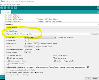
- add the ESP32/expressif package URL for the Boards Manager, as nicely explained here; essentially, select menu File -> Preferences, then add line
https://raw.githubusercontent.com/espressif/arduino-esp32/gh-pages/package_esp32_index.json
to input box "Additional Boards Manager URLs".
- install the set of ESP32 boards in "Boards Manager"; menu Tools -> Boards Manager:
- select the proper board for the ESP32-WROOM dev kit that I used; menu Tools -> Boards Manager -> ESP32 Arduino -> Node32s;
- open the sketch, then modify the SPI pins (I used DIN=33, CLK=12, CS=13, RST=27, all on the same side of the ESP32 dev module); got compilation error "Library not found" for both NTPClient and TimeLib;
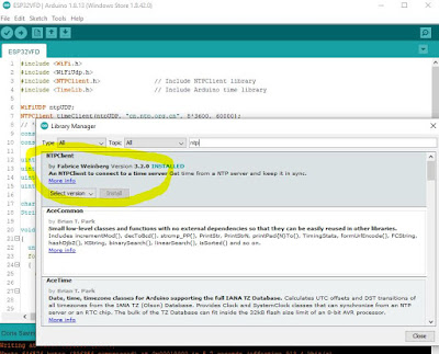
- install the missing libraries, through menu Tools -> Manage Libraries...
The 2 libraries have been installed here
at the location specified in File -> Preferences:
- compile, then upload successfully.
Surprisingly easy, straightforward and without glitches, this must have been the easiest ever first-time interfacing with a device.
Compared to the HDSP-2534 LED display, the characters in the VFD module are about 50% bigger, and much brighter, making it readable from a greater distance. The current consumption is in the range 100-200mA, versus about 20mA taken by the HDSP display.
Also, at just about US$13, this (yet unnamed, or maybe Futaba?, see photo below) VFD display makes a great functional alternative for the more expensive HDSP/Avago/Siemens/Osram 8-character LED displays.
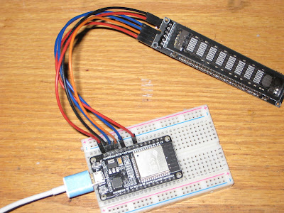
For the record, this was my setup:
And the (modified, barebone) sketch:
#include <WiFi.h>
#include <WiFiUdp.h>
#include <NTPClient.h>
#include <TimeLib.h>

WiFiUDP ntpUDP;
NTPClient timeClient(ntpUDP, "cn.ntp.org.cn", 8*3600, 60000);
const char *ssid     = "<wifinet>";
const char *password = "<password>";

uint8_t din   = 33; // DA
uint8_t clk   = 12; //23; // CK
uint8_t cs    = 13; //19; // CS
uint8_t Reset = 27; //22; // RS

char *str_time = "00:00:00";
String format_time = "00:00:00";

void write_6302(unsigned char w_data)
{
  unsigned char i;
  for (i = 0; i < 8; i++)
  {
    digitalWrite(clk, LOW);
    if ( (w_data & 0x01) == 0x01)
    {
      digitalWrite(din, HIGH);
    }
    else
    {
      digitalWrite(din, LOW);
    }
    w_data >>= 1;
    digitalWrite(clk, HIGH);
  }
}

void VFD_cmd(unsigned char command)
{
  digitalWrite(cs, LOW);
  write_6302(command);
  digitalWrite(cs, HIGH);
  delayMicroseconds(5);
}

void S1201_show(void)
{
  digitalWrite(cs, LOW);
  write_6302(0xe8);
  digitalWrite(cs, HIGH);
}

void VFD_init()
{
  // set number of characters for display;
  digitalWrite(cs, LOW);
  write_6302(0xe0);
  delayMicroseconds(5);
  write_6302(0x07);  // 8 chars;
  digitalWrite(cs, HIGH);
  delayMicroseconds(5);

  // set brightness;
  digitalWrite(cs, LOW);
  write_6302(0xe4);
  delayMicroseconds(5);
  write_6302(0x33); // level 255 (max);
  digitalWrite(cs, HIGH);
  delayMicroseconds(5);
}

void S1201_WriteOneChar(unsigned char x, unsigned char chr)
{
  digitalWrite(cs, LOW);
  write_6302(0x20 + x);
  write_6302(chr + 0x30);
  digitalWrite(cs, HIGH);
  S1201_show();
}

void S1201_WriteStr(unsigned char x, char *str)
{
  digitalWrite(cs, LOW);
  write_6302(0x20 + x);
  while (*str)
  {
    write_6302(*str); // ascii
    str++;
  }
  digitalWrite(cs, HIGH);
  S1201_show();
}

void setup()
{
  WiFi.begin(ssid, password);
  Serial.begin(115200);
  Serial.print("Connecting.");
  while ( WiFi.status() != WL_CONNECTED ) {
    delay(500);
    Serial.print(".");
  }
  Serial.println("connected");

  timeClient.begin();

  pinMode(clk, OUTPUT);
  pinMode(din, OUTPUT);
  pinMode(cs, OUTPUT);
  pinMode(Reset, OUTPUT);
  digitalWrite(Reset, LOW);
  delayMicroseconds(5);
  digitalWrite(Reset, HIGH);
  VFD_init();
}

void loop()
{
  timeClient.update();
  format_time = timeClient.getFormattedTime();
  char *str_time = &format_time[0];
  S1201_WriteStr(0, str_time);
  Serial.println(timeClient.getFormattedTime());
  delay(1000);
}
Next step should be researching the PT6302 command set, finding out how to adjust brightness and others.


