Showing posts with label OLED. Show all posts

Thursday, June 3, 2021

Assembling the Pro Mini OLED clock shield kit

Customers complained about the lack of documentation on the Pro Mini OLED clock kit.

I listened and I agree. Even though the silkscreen should provide the necessary directions for soldering the parts on the shield itself, adding the Pro Mini board and the OLED display are still ambiguous, especially because there are multiple options.

Here is a quick, but hopefully adequate, step-by-step guide on one way to assemble this clock kit.

1. Make sure you source the correct Pro Mini board, that looks similar to the one in the photos below. It features an ATmega328 clocked at 16MHz.

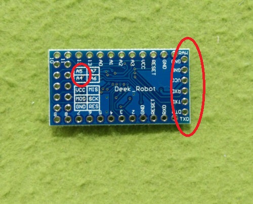
Note that SCL and SDA (A5, A4 respectively) are broken out. Also, the FTDI connects directly to the side of the Pro Mini board.


2. Program the board itself with the OLED Clock sketch. In Tools/Board, select "Arduino Duemilanove w/ ATmega328". Upload using the FTDI adapter. This step is important because you want to make sure your Pro Mini works before you mount/solder it.

3. Make sure you source the correct I2C 128x64 OLED display, like the one shown below.


The pins at the top must be in the order (left to right) VCC-GND-SCL-SDA or VCC-GND-SDA-SCL.

In case your display has a different arrangement of the pins, e.g. GND-VCC-SCL-SDA, you will need to swap the leftmost two pins, by rewiring the traces (cut, then reconnect) on the shield's PCB (not on the display, which remains untouched), as explained in Step 6.

4. Solder the DS1307, paying attention to the correct orientation (notch up), then the 2 resistors and the crystal.

5. Solder the 2 jumper bridges according to the OLED display you are going to use.


If your OLED has pin 3 and 4 configured as SCL and SDA respectively, then solder the right bridge of the left jumper and the left bridge of the right jumper (see the photo below).


6. Only if necessary
Remember, the Pro Mini OLED shield was designed for I2C OLED displays that have pin 1 as VCC and pin 2 as GND. If that is not the case (as in the photo below),

those first 2 pins must be rewired, as shown (after the traces had been cut and pins isolated).


7. Solder the Pro Mini board on top and close to the OLED shield, using machined male pins (included in the kit). Only the relevant pins, highlighted in the photo below, need to be soldered.


Pay attention, since this is a hard-to-reverse move. Fixing a mistake here involves de-soldering. Also, the parts underneath cannot be (easily) accessed anymore.

8. Solder the 4-pin female header, the 2 buttons and the battery holder, then insert the CR1225 battery, with the correct polarity (+ on top).


9. Insert the OLED display.

10. Power the clock through the FTDI breakout (observe the correct orientation) or by directly wiring VCC and GND to a 5V or battery source.
Any of the 5 clock faces can be selected by pushing simultaneously the 2 buttons.
Pressing each button individually will increment either the hours or the minutes.


Sunday, February 7, 2021

Enclosure ideas for WiFiChron and other clocks

It turns out that most electronics, even prototypes, can be easily enclosed with Lego. And that means no screws, no glue, no fasteners, zero tools, just the bricks and some imagination.

This is the HDSP clock variant with 1" displays driven by HT16K33 (introduced here). The board was cut and filed (0.5mm on each side) to fit snug between the walls (see this).


Next is a HDSP clock variant with two Adafruit Quad Alphanumeric displays.


Similarly, the PCB was cut and filed a bit. The assembly fits solidly between the bricks (no movement when shaken). As in the previous build, the exposed PCB is kind-of-required to allow access to the two buttons (set hours, set minutes).

Both of the above can be mounted on a Lego wall (as found in schools) or they can desk-stand on their own.

Here is an example of a Lego-encapsulated WifiChron.


The PCB was also filed about 0.5mm on each side to fit between the lateral brick walls. It did not have to be fastened in any other way. The ESP8266 module fits inside nicely. The 3 buttons and the USB mini B connector are all easily accessible from the back.

Below is the Lego version of the Axiris clock.


Since it does not have any buttons, the time is set through Bluetooth (command "SET TIME=hh:mm", sent from Terminal app while BT paired).

And finally, a couple of OLED clocks, both running the same software on similar hardware: pro-mini + OLED shield and wsduino + 2.42" OLED shield, respectively.


Note that this is the prototype version, using a LiPo battery with charger (similar to the one shown here).


Again, all the above enclosures feel solid: nothing moves or rattles when upside down or even shaken. I did not try dropping them though :)

And lastly, the WiFiChron with Adafruit quad 0.56" displays from the previous post, sandwiched between scrap plexiglass plates:


Monday, July 20, 2020

Arduino OLED display shield

The 2.4" I2C OLED display I had sitting idle is too big for the "Promini OLED Clock shield", yet a perfect candidate for a regular Arduino shield. This is how it looks soldered on a prototype shield with two buttons on top, attached to wsduino running the OLED Clock sketch (each of the 5 faces shown):


The current sketch uses U8glib library and takes about 27k of ATmega328's 31k program memory. It could be enhanced by adding alarm (buzzer, relay etc.), since most of the digital pins are available (only D3 and D9 are used for the 2 buttons). Adding NTP time sync (with an ESP8266 module) could also be done, but one/some of the faces will need to be dropped because of memory constraints. All these are exercises/homework for the inquiring minds :)

Note: My nice beveled 2.42" OLED does not seem to be so ubiquitous.


 A quick search on ebay for similar 2.42" OLED displays returns a different style, already mounted on a larger PCB:


This may fit on the Arduino protoshield, but it may look bulky.

Thursday, October 23, 2014

OLED clock with Pacman mode

This large 2.42" OLED I2C module can be used as a replacement for the smaller 0.96" display for which I originally designed the ProMini OLED clock shield. It is built around the same SSD1306 chip, and it only comes in yellow (for now).

MikeM wrote this great Pacman clock sketch for it (available for download here), shown in the video below.


To display on the OLED, Mike used U8glib graphic library. Initially tested on the 0.96" OLED, the sketch froze after some time, for a yet to be explained reason. The same sketch works perfectly with the 2.42" display. Mike spent a lot of time trying to figure out if the culprit is software (bug in the U8glib) or hardware.
(Any feedback on this issue is greatly appreciated.)

The clock can also display the time as HH:MM:SS on the whole screen, as shown in the photo below, also courtesy of Mike.


My next step would be to design an enclosure for it. For that I will probably need some more help :)

Update Nov 29, 2014, from MikeM:
A lot of credit goes to MikeR, I took the Tetris and Pacman faces from his sketch and adapted them for the OLED shield.  The Pong code is modified from the WiseClock sketch.  The digital, analog, and QR code faces are mine, although I did use a QR code library I found.  I did credit MikeR inside of the code.

Saturday, August 30, 2014

ProMini clock shield with OLED display

Yet another ProMini clock shield kit, this time featuring a 128x64 I2C OLED display.


The kit can be purchased with or without the OLED display (I prefer you buy the OLED on your own, for example this excellent one from miker).

  US$30, includes OLED display, free shipping to North America

  US$16, OLED not included, free shipping to North America

The kit includes:
  • PCB
  • DS1307 SMD
  • 32kHz crystal
  • CR1220 coin battery
  • battery holder
  • optional: I2C 128x64 OLED display (blue or white)
  • tactile switch (2x)
  • resistor 10k (2x)
  • machined male pins


The PCB was designed to accommodate I2C OLED displays with the 4-pin header configured either as VCC-GND-SDA-SCL or as VCC-GND-SCL-SDA.

The OLED clock can also be powered from the same LiPo battery shield for ProMini, as used in the bubble clock. To minimize current consumption (beside disabling the ProMini on-board LEDs), the processor can be awaken from sleep at the push of the "hours" button (on D3).

Schematic and board layout are shown below.


The OLED clock could show the time in many different ways, including Pong mode (sketch adapted from miker), analog clock mode, digital clock mode (sample sketches to be provided soon).

Friday, May 30, 2014

My review of bGeigie Nano from Safecast

I finally finished assembling, after more than a year, my bGeigie Nano. At over $400, this was by far the most expensive Arduino project I have built to date.


The feature-rich open-source Geiger counter is offered as a kit by Medcom for the price of $450 (of which, $75 is donated to Safecast organization). I stubbornly insisted on sourcing the parts on my own, to save a few bucks and to get a closer look at the process. Let me tell you: this may be the only kit out there where the components bought individually are as expensive as the kit itself! Obviously, this kit was not designed to make a profit.


Here is a price breakdown (for non-believers):
- PCB (OSHPark) - $17 (3 for $52)
- Pelican 1010 box (store) - $13
- Arduino Fio - $25
- GPS module - $40
- OpenLog - $25
- OLED display - $25
- laser-cut plates - $25
- sensor LND7317 - $150
- iRover HV supply - $35
- LiPo battery - $10
- SD card - $10
- other electronic components - $5
- hardware (standoffs, screws etc) - $5
- shipping (on some of the items) - $30
-----------------------------
Total = $415


Since it took me so long to build it, I forgot a lot of details (I know, I should have logged impressions along the way; that's why it's called "web log").
But here are a few things I can still remember:
  • the kit is pretty easy to build (once one has all components); geared towards the novice maker, the only challenge is to follow the assembly instructions, sometimes not very clear because it lacks details (for example, the spacers's sizes; although this does not matter for those who buy the kit); but it seems that the instructions are periodically updated and improved;
  • the support and discussion forum is great; I got quick and helpful answers to all my questions;
  • the display is 128x64 OLED, even though the resolution used is 128x32 (notice in the photo above that every other line is blank)
  • the sketch can barely fit in the 30KB program space of Fio's ATmega328 (I actually may have commented out some functionality to make it fit);
  • at the time I started, the Geiger sensor was not offered for sale (now it is); I bought it directly from Medcom, together with the high-voltage power module; they did not include the protection grid that comes with the kit;
  • a big surprise was that the assembly fits perfectly in the Pelican box, without using the rubber lining (which I had cut and prepared according to the instructions anyway). When I say "perfectly" I mean nothing rattles inside when the box is shaken. Truly remarkable. For those interested, I used M3x10mm standoffs between the 1.5mm plates, with the bottom one separated with a set of 1mm washers (see photo below, taken before I installed the battery and the sensor).
  • the toggle switch at the top would be a better candidate as power switch than the slide switch currently used (main reason being that the mechanical life of the NKK switch  is longer than the life of the generic slide switch; it also feels more reliable); maybe a future version will swap those two switches;
  • bluetooth could be used to connect to smart phone rather than the current cable solution; but that would require a larger sketch running on a bigger processor (ATmega1284 would be a good candidate);
  • although the modules used come with headers, once installed, they cannot be removed (because they are soldered, for mechanical/space reasons; the only exception is the OLED display); removable modules would make the device easier to debug and fix (if necessary);
  • overall, it was a good experience; I used some modules for the first time; I learned a few things (for example, how useful the double-sided foam tape can be); it opened perspectives to new ideas; thank you guys!

Saturday, February 8, 2014

Altoids Geiger counter

My "Remixed Geiger counter" board fits almost perfectly, by chance, in the "classic" Altoids box, with room left for the SI-29 GM tube, the 1100mAh LiPo battery and the 0.96" OLED display.


The ATmega328 processor runs at 8MHz with the internal oscillator, a better choice (than the 16MHz of Arduino 2009) for the LiPo voltage of approx 3.7V.  The display I used is compatible with the monochrome 128x64 OLED display from Adafruit.
It is powered at 3V3, requiring a voltage regulator (78L33, TO-92), placed where the the trim-pot (for adjusting LCD contract) was supposed to be (top-right corner of the board).

The sketch uses Adafruit_SSD1306 library, with the wiring to the display as defined below:

#define OLED_DC 8
#define OLED_CS 7
#define OLED_CLK 4
#define OLED_MOSI 3
#define OLED_RESET 5

Note that the same D3-D8 are used for connecting to the LCD 1602 display in the "regular" DIYGeigerKit.
Also note that I did not install the "click" LED nor the buzzer, relying instead on the OLED display to indicate the radiation level.

Since the lid needs to be open anyway in order to see the screen, I thought it does not make sense to drill 2 holes in the box for the USB miniB connector (used for charging the battery) and the on/off switch. (As well, this sounds like a believable excuse for being lazy.)


If I were to improve on it, I would replace the right-angle toggle switch with a straight-up one (easier to operate), then add a button or two for user inputs (configuration parameters, menu navigation etc). The "click" buzzer and the LED could be made "digital", wired to controller's outputs. Adding a Bluetooth module would be also useful (if it works at all from inside the closed box, I need to try it). Ideally, I would also add RTC, GPS and SD card, for logging purposes. And then it would become a smaller and cheaper version of Safecast bGeigieNano :)