Showing posts sorted by relevance for query axiris. Sort by date Show all posts

Friday, July 3, 2015

Wiseduino Next Generation

You have a "tube shield" like the Axiris IV3 shield or the Nixie shield and you want to make a clock. You will definitely need an Arduino. You can either program it to (roughly) count the seconds, minutes, hours, or you can add an extra RTC, specialized in (accurate) time keeping, and program your Arduino to just get the time from RTC. The latter is Wiseduino, the first board I ever designed (also discontinued a long time ago). I badly needed one to finish the Axiris IV3 clock, since neither the software solution (second-counting) nor the hardware solution (adding a second RTC shield) was suitable. And so I re-designed it, improved on existing features (power, RTC) and added new ones (support for XBee/BTBee/GPSBee). This new version, spelled "wsduino" (but still pronounced "wiseduino") is shown below, next to the Axiris IV3 shield.


The wsduino board has an Arduino-compatible footprint, so it fits perfectly in the Axiris-designed-and-made enclosure (which I got as a gift from Nick :).


As you notice from the photo, the crystal is optional. Lately, I prefer to run the ATmega328 processor with the internal oscillator at 8MHz. The fewer the parts, the fewer the points of failure (and also cheaper). The wsduino board can be powered from either the USB miniB connector, or from the barrel connector, through a 7805 voltage regulator, selectable with a jumper. The board also has a 500mA 3V3 regulator, soldered on the bottom.

The DS3231 RTC is also soldered on the bottom. An XBee-footprinted serial device is connected to Rx/Tx of ATmega328, with voltage-divider level-shifting for Tx (pin D1). For the Axiris clock, I used the BTBee as a way to set the time and date, since the enclosure was not designed with buttons in mind. The sketch can be found here.


The photo below shows a couple of wsduino bare boards, top and bottom.


wsduino kit can be purchased here.

Monday, July 24, 2017

IV-3 VFD confusion

So you want to build Axiris's IV-3 shield for Arduino, sourcing the IV-3 VFD tubes yourself, from any of the numerous ebay sellers, as I did.

Firstly, it is important to note that, although the assembly manual for IV-3 shield refers to it as "IV-3/IV-3a/IV-6 VFD shield for Arduino", which would make you think one could install either IV-3, IV-3A or IV-6 tubes, this is not quite the case. The reason is the difference in pin configuration:
  • IV-3: 9-segment + dot, 14 pins (1 not connected)

(pin configuration is bottom view)
  • IV-3A and IV-6: 7 segment + dot, 12 pins (1 not connected)
(pin configuration is bottom view)
  • and then, there is IV-3 v-82, which I bought on ebay: 7 segment + dot, 14 pins (3 not connected)
(pin configuration is top view)

IV-3 v-82 (as I named it, based on the printing on the back of the tube), is an amalgamation between IV-3 and IV-3A:
- can be found in either 7 segment or 9 segment (+ dot), although only 7 segments are connected;
- has 14 pins (as to support a 9 segment digit + dot), with 3 not connected;
- pin sequence differs from both IV-3 and IV-3A;
- the "key" (the trimmed unconnected pin) is on the opposite side compared to IV-3/IV-3A.
Below are some photos, with the "axiris" IV-3A on the left.


(Also notice the color of the ceramic insulator, white for the "axiris" IV-3A, pink for the IV-3 v-82.)

To adapt the IV-3 v-82 tube to the Axiris board, the pins need to be scrambled like this:


which leads to this ugly assemblage:


It would probably work with proper heat-shrink tubing around the tube terminals, but I preferred to order the correct IV-3A for which the board was designed.

Conclusion: Pay attention when (and if) you order the tubes for "Axiris IV-3 VFD shield" separately. The sure bet is to order IV-3A, with the white ceramic insulator, and the trimmed pin on the right side (when looking at the digit).

P.S. Also, make sure the tubes are "mirrory" black at the top. If the top is white, then the tube is damaged for sure, air got in the tube (basically the tube's glass is cracked), like in the photo below (right tube is damaged).


Saturday, January 31, 2015

My experience with Axiris IV-3 shield for Arduino

I recently bought on ebay the PCB for this open source VFD shield, designed and made by Axiris, a company in Belgium. I was attracted by the solid documentation provided on their site, which includes the schematics (even Eagle files), assembly instructions, demo software, files for laser-cutting the enclosure. I should also mention the professional photos, rivaling those of the top sites (e.g. adafruit, sparkfun).

Assembly went smoothly, as expected. I also expected it to work on the first try, like the other two VFD devices I built previously, the Ice Tube Clock and the akafugu VFD clock. I guess I ran out of luck :)
But, as my kid would say, "losing is learning". This became an opportunity for me to actually go one step further than just soldering the components mindlessly (because the instructions are too easy :)

This is how I learned what fascinating little devices VFDs are. They function similar to cathode ray tubes (CRT), used in the previous generation of TVs: the filament gets heated (by about 1V, believe it or not(*)) and frees electrons; a thin grid, supplied with higher voltage, attracts these electrons and speeds them towards the anodes, which are conductors that become fluorescent when hit by these electrons.
VFDs are also similar in functionality to triodes, and probably can even be used as amplifiers (in a MacGyver-kind situation :).

Compared to Numitron tubes or even Nixies, VFDs are more complicated to drive, since they require two voltages: a very low one (around 1V) for the filament (cathode) and a higher one (between 5V and 60V, depending on the model) for the fluorescent anodes and the grid.

IV-3 tubes used in the Axiris shield require about 30V for the anodes and 0.85V for the filament. The power source to generate these two voltages is original (when compared to those in other successful VFD devices). The documentation gives a great explanation on how it works.

In any case, it only "half-worked" for me: I got the high voltage around 32V, but the tubes were still dark.
There were 2 possible causes for this:
  • either defective tubes (with burned filament) or
  • missing low voltage
Not being able to find a "troubleshooting guide", I contacted Axiris. After a few emails, their advice was to check C2 and C3 and eventually play a bit with their values (between 5 and 15 nF). Which I did, with no success.

Needless to say that the design of this power source is out of my league. The filament voltage is high-frequency AC, impossible to measure with a regular multimeter (**). But a VFD's filament, like a light bulb's filament, works with DC as well. So I tried lighting them up with 3 AAA batteries in series (since the 4 filaments are connected in series). I was able to see them glowing (until that moment I didn't even know where the tube's filament was). That did the trick and proved that the VFDs were not defective.


As an alternate (working) solution, I chose to replace the low voltage AC from the oscillator's power supply (which did not work for me) with the PWM voltage from the available D11. I cut the trace to VFIL1 (see schematics below) and re-wired to the anode of diode D1. I took out C2 and C3 (right hand side in the photo above) and connected a wire between VFIL2 and Arduino's D11.


With analogWrite(D11, 200), the 4 in-series filaments are now powered with a measurable 3.2V (3.9V from D11 minus 0.7V voltage drop on diode D1). This is not an outrageous solution when you think of switching power sources driven by pulses from uC used in some Nixie clocks.

With the hack in place, I was then able to successfully run Axiris' demo sketch (shown in action in the photo).
As they say, "all is good when it ends well".

What I would change or improve in this kit:
  • add the ability to adjust the high voltage with a trim-pot; for two reasons:
    • eliminates the restriction to use only a 12V power adapter to generate the required 30V;
    • the tubes' luminescence diminishes over time (I read); a higher anode voltage can bring the brightness back;
  • power the filaments independently (in parallel);
    • if the filament of one tube burns out for some reason, all tubes will go dark; finding which one is defective is not obvious, and will require a multimeter;
  • replace the 8-pin "power" header with a 6-pin header, to be able to plug the shield in the original Arduino 2009 as well; the left-most 2 pins are not used, yet Arduino's capacitors are touching one of them;
  • add a troubleshooting section;
    • include measuring the resistance between VFIL1 and VFIL2 being about 32 ohms; that proves that the filaments are intact;
    • include testing of the filaments with a battery for the common folks that lack an oscilloscope (for those who have one, include some info on the AC voltage);

In conclusion, I find this kit as a great introduction to VFDs. I think it is easier to understand how it works than the Ice Tube clock, since it's all discrete components (no IC driver). It is also a lot more software-hackable, being controlled by an Arduino sketch. It is more hardware-hackable through the use of Arduino shields, which may include an RTC, Bluetooth, buzzer etc.


(*) One can also start a fire with a AA (1.5V) battery.
(**) Nick, I am just one step away from using the oscilloscope you sent me. I promise to write a review on it soon.


Saturday, January 23, 2016

Break

I was going to say that this was the typical case of work/life taking precedence over hobbies. Not a good excuse though, since one can always find bits and pieces of time, like coins between couch cushions :). The best explanation for the long break is probably laziness. But I didn't just loiter around. With my desk full of just-started or half-finished projects screaming for time and attention, how could I? Here are some of the things I re-visited and tried to complete.

1. The Axiris IV-3 clock
As designed by Axiris team, the enclosure for the IV-3 shield can only accommodate one Arduino. The only way to make a real (with RTC) clock is to replace the Arduino with a wdsuino. Then, there is the issue of buttons (or any other way to set the time without using a PC, through USB). I managed to add an extra board that holds two buttons, accessible through the holes on the bottom side of the enclosure.
Below are some pictures.


The sketch I used is included below (based on the sample code from Axiris).

#include "Wire.h"
#include "DS1307.h"

#define PIN_BTN_SETHOUR 13
#define PIN_BTN_SETMIN  12

// globals; their values are set in getTimeFromRTC();
int hour;
int minute;
int second = 0;
int year, month, day;

// receive commands from serial port in this buffer;
char cmdBuffer[30] = {0};
byte nCrtBufIndex = 0;

// read time from DS1307 at intervals; for 5000, that's about 6 times a second;
#define MAX_TIME_READING_COUNTER  5000
long timeReadingCounter = MAX_TIME_READING_COUNTER;

/*
       pin 2
        ---
 pin 7 |   | pin 3
       |   |
 pin 8  ---
       |   | pin 4
 pin 6 |   |
        --- . pin 9
       pin 5
*/

static  byte  digit_seg_data[12*7] PROGMEM =
{
/* pin    2     3     4     5     6     7     8  */
        HIGH, HIGH, HIGH, HIGH, HIGH, HIGH,  LOW,    // Digit 0
         LOW, HIGH, HIGH,  LOW,  LOW,  LOW,  LOW,    // Digit 1
        HIGH, HIGH,  LOW, HIGH, HIGH,  LOW, HIGH,    // Digit 2
        HIGH, HIGH, HIGH, HIGH,  LOW,  LOW, HIGH,    // Digit 3
         LOW, HIGH, HIGH,  LOW,  LOW, HIGH, HIGH,    // Digit 4
        HIGH,  LOW, HIGH, HIGH,  LOW, HIGH, HIGH,    // Digit 5
        HIGH,  LOW, HIGH, HIGH, HIGH, HIGH, HIGH,    // Digit 6
        HIGH, HIGH, HIGH,  LOW,  LOW,  LOW,  LOW,    // Digit 7
        HIGH, HIGH, HIGH, HIGH, HIGH, HIGH, HIGH,    // Digit 8
        HIGH, HIGH, HIGH, HIGH,  LOW, HIGH, HIGH,    // Digit 9
         LOW,  LOW,  LOW,  LOW,  LOW,  LOW, HIGH,     // Hyphen
         LOW,  LOW,  LOW,  LOW,  LOW,  LOW, LOW      // empty/not lit at all
};

typedef  struct  _TUBE
{
  byte    digit;      // 0..9
  byte    dot;        // HIGH or LOW
}
TUBE;

// Display state of the tubes (read-write): {digit, dot}
static  TUBE  tube_list[4] =
{
  { 10,  LOW },
  { 10,  LOW },
  { 10,  LOW },
  { 10,  LOW }
};

// Variables accessed at interrupt level
static  byte    cur_tube = 3;        // 0..3

ISR(TIMER1_COMPA_vect)
{
  const  byte  *digit_seg_p;
  byte          digit;
  byte          pin;

  // Clear pins as fast as possible
  PORTC &= ~0b00001111;  // Clear pin A[0..3]
  PORTD &= ~0b11111100;  // Clear pin 2..7
  PORTB &= ~0b00000011;  // Clear pin 8..9

  __builtin_avr_delay_cycles(8*40);  // 40 us (at 16 MHz)

  // Select the next tube
  cur_tube++;
  cur_tube %= 4;

  digit = tube_list[cur_tube].digit;
  digit_seg_p = digit_seg_data + 7*digit;
  for (pin = 2; pin < 9; pin++, digit_seg_p++)         digitalWrite(pin,pgm_read_byte(digit_seg_p));
  digitalWrite(pin,tube_list[cur_tube].dot);

  // Enable the current tube
  digitalWrite(A0+cur_tube,HIGH);
}

void  setup ()
{
  Serial.begin(9600);
  pinMode(A0,OUTPUT);
  pinMode(A1,OUTPUT);
  pinMode(A2,OUTPUT);
  pinMode(A3,OUTPUT);
  pinMode(2,OUTPUT);
  pinMode(3,OUTPUT);
  pinMode(4,OUTPUT);
  pinMode(5,OUTPUT);
  pinMode(6,OUTPUT);
  pinMode(7,OUTPUT);
  pinMode(8,OUTPUT);
  pinMode(9,OUTPUT);
  pinMode(10,OUTPUT);

  // Turn on the LEDs
  digitalWrite(10,HIGH);

// (fc) filaments, for my special case; normally this is not needed;
  pinMode(11,OUTPUT);
// power the filaments;
  analogWrite(11, 200);

  // set-time buttons;
  pinMode(12, INPUT_PULLUP);
  pinMode(13, INPUT_PULLUP);

  cli();

  // We've observed on Arduino IDE 1.5.8 that TCCR1A is non-zero at this point. 
  // So let's play safe and write all relevant timer registers.
  TCCR1A = 0b00000000;

// (fc) half the number for 8MHz Arduino
//  OCR1A  = 250-1;       // 250 Hz (62500/250)
  OCR1A  = 125-1;       // 250 Hz (62500/250)

  TCNT1  = 0;
  TIMSK1 = 0b00000010;
  TIFR1  = 0b00000000;
  TCCR1B = 0b00001100;  // Enable timer

  sei();
}

void loop()
{
  checkButtons();
  
  timeReadingCounter++;
  if (timeReadingCounter > MAX_TIME_READING_COUNTER)
  {
    getTimeFromRTC();
    display_time();

    timeReadingCounter = 0;
  }
}

static void display_time()
{
  unsigned long   ms = millis() % 1000;
  boolean        dot = (ms < 500) ? HIGH : LOW;
  byte            u;

  cli();
  u = hour;
  tube_list[1].digit = (u % 10);
  tube_list[1].dot = dot;

  tube_list[0].digit = ((u/10) ? u/10 : 11);
  tube_list[0].dot = LOW;

  u = minute;

  tube_list[3].digit = (u % 10);
  tube_list[3].dot = LOW;

  tube_list[2].digit = (u / 10);
  tube_list[2].dot = LOW;

  sei();
}

void getTimeFromRTC()
{
  int rtc[7];
  RTC_DS1307.get(rtc, true);

  // check to avoid glitches;
  if (rtc[DS1307_MIN] < 60 && rtc[DS1307_HR] < 24 && rtc[DS1307_SEC] < 60)
  {
    second = rtc[DS1307_SEC];
    minute = rtc[DS1307_MIN];
    hour   = rtc[DS1307_HR];
  }

  // check to avoid glitches;
  if (rtc[DS1307_YR] <= 2050 && rtc[DS1307_MTH] <= 12  && rtc[DS1307_DATE] <= 31)
  {
    day    = rtc[DS1307_DATE];
    month  = rtc[DS1307_MTH];
    year   = rtc[DS1307_YR];
  }
}

void setTime(int hh, int mm, int ss)
{
  getTimeFromRTC();

  // NOTE: when setting, year is 2 digits; when reading, year is 4 digits;
  RTC_DS1307.stop();
  RTC_DS1307.set(DS1307_SEC,  ss);
  RTC_DS1307.set(DS1307_MIN,  mm);
  RTC_DS1307.set(DS1307_HR,   hh);
  RTC_DS1307.set(DS1307_DOW,  1);
  RTC_DS1307.set(DS1307_DATE, day);
  RTC_DS1307.set(DS1307_MTH,  month);
  RTC_DS1307.set(DS1307_YR, year > 2000? year-2000 : year);
  RTC_DS1307.start();
}

void setDate(int newyear, int newmonth, int newday)
{
  getTimeFromRTC();

  // NOTE: when setting, year is 2 digits; when reading, year is 4 digits;
  RTC_DS1307.stop();
  RTC_DS1307.set(DS1307_SEC,  second);
  RTC_DS1307.set(DS1307_MIN,  minute);
  RTC_DS1307.set(DS1307_HR,   hour);
  RTC_DS1307.set(DS1307_DATE, newday);
  RTC_DS1307.set(DS1307_MTH,  newmonth);
  RTC_DS1307.set(DS1307_YR,   newyear);
  RTC_DS1307.set(DS1307_DOW,  1);
  RTC_DS1307.start();
}

void checkButtons()
{
  // increment hours and minutes;
  if (LOW == digitalRead(PIN_BTN_SETHOUR))
  {
    hour++;
    if (hour>23) hour = 0;
    setTime(hour, minute, 0);
    delay(200);
  }
  if (LOW == digitalRead(PIN_BTN_SETMIN))
  {
    minute++;
    if (minute > 59) minute = 0;
    setTime(hour, minute, 0);
    delay(200);
  }
}

2. WiFiChron1284 edition, featuring ATmega1284 SMD
This should be the "ultimate" upgrade for the WiFiChron board. The ATmega1284 processor will provide extra room for the ESP8266 WiFi code (debugging, parsing RSS feeds, data buffering etc).
The PCB design of the new board is shown below. (The boards are ordered and being manufactured).


3. Adapter for dual HDSP display
This adapter, suggested by Ray S, is the new addition to the collection of adapters developed for HDSP clock or WiFiChron.
Combined with the above mentioned WiFiChron1284, it would make a miniature Wise Clock 4 (without the SD card though). The two HDSP-2534 displays share all signals except for the CE (chip enable). The second display uses pin 10 for CE. Writing to each display is done by enabling the right CE line. This allows independent control of each display (dimming, text scrolling etc.).

Photos of the prototype are shown below.


Sunday, February 7, 2021

Enclosure ideas for WiFiChron and other clocks

It turns out that most electronics, even prototypes, can be easily enclosed with Lego. And that means no screws, no glue, no fasteners, zero tools, just the bricks and some imagination.

This is the HDSP clock variant with 1" displays driven by HT16K33 (introduced here). The board was cut and filed (0.5mm on each side) to fit snug between the walls (see this).

Next is a HDSP clock variant with two Adafruit Quad Alphanumeric displays.


Similarly, the PCB was cut and filed a bit. The assembly fits solidly between the bricks (no movement when shaken). As in the previous build, the exposed PCB is kind-of-required to allow access to the two buttons (set hours, set minutes).

Both of the above can be mounted on a Lego wall (as found in schools) or they can desk-stand on their own.

Here is an example of a Lego-encapsulated WifiChron.


The PCB was also filed about 0.5mm on each side to fit between the lateral brick walls. It did not have to be fastened in any other way. The ESP8266 module fits inside nicely. The 3 buttons and the USB mini B connector are all easily accessible from the back.

Below is the Lego version of the Axiris clock.


Since it does not have any buttons, the time is set through Bluetooth (command "SET TIME=hh:mm", sent from Terminal app while BT paired).

And finally, a couple of OLED clocks, both running the same software on similar hardware: pro-mini + OLED shield and wsduino + 2.42" OLED shield, respectively.


Note that this is the prototype version, using a LiPo battery with charger (similar to the one shown here).


Again, all the above enclosures feel solid: nothing moves or rattles when upside down or even shaken. I did not try dropping them though :)

And lastly, the WiFiChron with Adafruit quad 0.56" displays from the previous post, sandwiched between scrap plexiglass plates:


Sunday, July 5, 2015

Introducing wsduino

This project is actually a revisit of my old Wiseduino, with the same goal: an Arduino-compatible with on-board Real Time Clock, and some extras (in this case, an XBee-like device, e.g. BTBee, GPSBee, WiFly). I renamed it "wsduino", although the pronunciation should remain the same :)

I redesigned wsduino mainly for the Axiris IV3 clock, whose enclosure allows for only 2 boards (Arduino + IV3 shield), with openings for power socket, USB, and no accessible buttons. Essentially, wsduino saves you an extra shield, which would have hosted the RTC (+backup battery) and the XBee.

 US$27 - free shipping to North America

wsduino is now available as a kit, as shown in the photo below.


The wsduino kit includes:
  • PCB
  • ATmega328 processor with bootloader
  • 28-pin socket
  • 16MHz crystal
  • 2 x 22pF capacitor
  • power jack
  • 7805 voltage regulator
  • 1N4001 diode
  • USB miniB socket
  • DS3231 RTC (SMD)
  • A1117 3V3 regulator (SMD)
  • CR1220 battery + holder
  • 4 x 10k resistor
  • 4k7 resistor
  • 3 x 100nF capacitor
  • 47uF/25V capacitor
  • 47uF/16V capacitor
  • 470uF/10V capacitor
  • 2 x 10-pin 2mm female header for XBee
  • 40-pin 0.1" female header
  • 3-pin header + jumper (selection of power source)

An FTDI breakout is required to upload sketches.

Although the assembly is quite trivial, I enumerate below the steps, for the detail-oriented :)
  1. solder the DS3231 SMD chip on the bottom of the PCB, making sure the chip orientation is correct;
  2. solder the A1117 chip, also on the bottom of the PCB;
  3. solder the resistors R1-R4 (their values are shown in silkscreen);
  4. solder the IC socket, with the correct orientation of the notch; then insert the ATmega328 chip (after you bent the two sides of pins on a flat surface, one side at a time, to become parallel);
  5. solder the crystal (orientation does not matter)
  6. solder the USB miniB socket;
  7. solder the 7805 voltage regulator to match its shape in silkscreen;
  8. solder the ceramic capacitors (orientation does not matter);
  9. solder the 3 electrolytic capacitors, paying attention to their orientation;
  10. solder the diode, also paying attention to its orientation;
  11. solder the power jack;
  12. solder the 2 XBee headers;
  13. cut, then solder, the extension headers;
  14. solder the battery holder, then insert the battery.
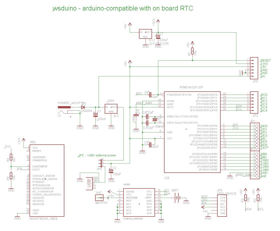
Schematic and board layout are shown below.


Here are some photos of the assembled board.

A  minimal wsduino is shown below, with the ATmega328 running on the internal oscillator at 8MHz, powered directly through the USB miniB socket.


The RTC (DS3231) and 3V3 voltage regulator are soldered on the bottom.


Perfect Arduino-compatible to quickly build a clock. Just add a display shield :)