Showing posts with label Wise Clock 2. Show all posts

Sunday, October 23, 2011

WiseClock / BookClock with I2SD - part 2

As promised, I am returning with the sketch (download from here).


Justin and Wyolum Co. also promised (wink, wink) that the next revision of I2SD will have the needed digital pins accessible through headers.

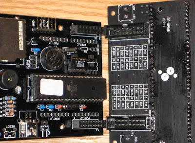
This "mixed breed wise clock" is using the I2SD (with on-board RTC and SD card), the display (and idea) from Book Clock, and code borrowed and adapted from Wise Clock 2.

Missing are the user buttons and a tilt switch, which may be connected to the free A0/D15 - A3/D18 pins available on the header of the I2SD board. (Note: The buttons and the tilt switch should be also supported in software as well, code which can be copied from the existing Wise Clock 2 and Book Clock sketches.)

Tuesday, March 15, 2011

Wise Clock 2 with Pong and other features

The latest release of the Wise Clock 2 software is now available for download.

It includes the following new features:
  • "Pong clock" (adapted to 16x24 display from Nick's version for 16x48 display);
  • ability to set the date (year/month/day) and day-of-week from the buttons (the "old" way of setting the clock through the file time.txt on the SD card is still there);
  • "Big clock", courtesy of Ruud;
  • display the temperature (for Duino644+ boards using the DS3231 real time clock).

The following animation (click on the photo) shows all menu options (displayed by pressing the button "Menu").


The existing attempt to a "user manual" still has valid information, so please browse through that too.

The software was compiled with Arduino IDE 21. After downloading it, the file should be unzipped in the folder "arduino21/libraries/". It is confirmed that both WiseClock2 and WiseClock3 software cannot co-exist in the same "libraries" folder.

In order to build, you will need the Sanguino files. Please refer to this post on the environment setup for the build/upload.

The code can handle both the red and the green 24x16 LED displays from Sure Electronics. The current default setting is for the green display. If you have the red display, comment out this line

#define _GREEN_DISPLAY_

in file HT1632.cpp.


Regarding setting the date, this is performed through the "DATE" menu option. The bottom half will show the date in the format YYMMDD. Move between the three by pressing the "Set" (middle) button. The flickering number indicates the current selection that gets incremented by pressing the "Plus" button. Note that the year (first 2 digits) will rollback after 50, so if you accidentally passed the current year (11), you will need to go all the way to 50, then back to 0, then to 11 again.

The day-of-week can be set through the menu "DAY". After the menu was selected (button "Set", the middle one), scan through the days by pressing button "Plus".

To save the settings, wait for the menu to timeout (after about 4 seconds after the last button press).

The display of the temperature is enabled/disabled from the menu options "TMP+" / "TMP-" respectively.

Other nice-to-have features on the TODO list:
- indicate special dates (e.g. friends' or family birthdays, anniversaries, holidays);
- automatic daylight-saving-time adjustment;
- chime at top and bottom of the hour.


Related posts:

Tuesday, February 1, 2011

Naming conventions

This is becoming a bit confusing even for myself. I could not find a name for the board powering the "Wise Clock 3", so I just named it "Wise Clock 3" board. On the other hand, the board that powers "Wise Clock 2" is Duino644. It sounds a bit silly, I know. I am still debating on the name for the new board and I am also open to suggestions. Until I find a better name, here is some help to clear the confusion.


"Wise Clock 3" is pictured on the left. It has a wider display (32x16, bi-color). The green board, as I mentioned, is called (for now) "Wise Clock 3 board".

"Wise Clock 2" is on the right side of the photo. It has a 24x16 single-color (either red or green) display. It is powered by the black board, named "Duino644".

Both Wise Clock 2 and Wise Clock 3 have similar functionality, but the latter has more features allowed by the bigger and better display. In the photo below they are working side by side.


Related posts:

Thursday, January 27, 2011

Wise Clock 2 now with redesigned Duino644

Update Apr 15/2011 - Added schematic.

A new revision (2.1) of Duino644 is now available. The redesigned board features:
  • real time clock could be either DS3231 (extremely accurate RTC from Maxim) or the "old" DS1307;
  • the resistor-based voltage dividers for SD card have been replaced by 74AHC125 buffer chip;
  • small prototyping area, for adding extra functionality (e.g. automatic dimming with photo-resistor, FM radio etc);
  • power-indicator blue LED is now through hole (replaces the SMD).


Still in place are:
  • ATmega644P (DIP package) with 40-pin socket;
  • SD card socket;
  • infrared receiver;
  • piezoelectric buzzer;
  • 3 push buttons;
  • reset button;
  • two 2x8-pin connectors for direct plug-in with the 2416 LED display from Sure Electronics;
  • miniB USB as power connector;
  • ISCP 6-pin header;
  • 6-pin FTDI header;
  • four 8-pin headers for expansion boards ("shields").

The photo below shows the assembled board.


But don't get too excited: there are also 2 "minor" (easy to fix, fortunately) glitches:
  1. the FTDI header is too close to the display connector, so that the board cannot be inserted completely into the display, unless a piece of plastic from the display's connector is chopped off, as shown below.
  2. pin 3 of DS3231 (INT/SQW) is connected directly to D2 (pin 3) of ATmega644P, as is the output of the IR receiver. Basically, the IR receiver and DS3231 INT/SQW share the same interrupt. I initially thought of having a switch (2-pin header shunt) to connect INT/SQW to D2, but I got carried away and forgot to add it. There are 2 fixes for this: either software (modify the ISR) or just cut off the trace (and keep the software unmodified).


If you buy the complete Wise Clock 2 kit, I will cut both the display connector and the trace for you.
Otherwise, the Duino644 kit will have the unaltered board.


Wednesday, December 8, 2010

Troubleshooting Wise Clock 2

It happened to me (and to others as well) that sometimes, after uploading the sketch, Wise Clock 2 displays the message "Failed to read quotes.txt from SD card" even though the SD card is inserted and has the right files on it. Obviously, this is a problem. First impulse is to try another SD card (and another and another). Still same error. Panic.

Here is a list of points to follow in this case.
  • check that all components are soldered (believe it or not, it happened to me once that I forgot to solder the 3V3 voltage regulator);
  • check that all pins of the SD socket are soldered; since the kit comes with the SD card socket already soldered (by myself), any un-soldered pins is my fault (I apologize in advance if that happens; it did happen);
  • with the multimeter, check all connections to the SD socket;
  • make sure that the resistors in the voltage divider (4K7 and 10K, under the microcontroller) are correctly placed, as shown in photo 4 in the posting "Assembling Duino644".

Here is a tip on how to find out easily the polarity of a LED (especially useful for SMDs, either in circuit or not): with the multimeter's switch on the "check continuity" position (beeps), measure the "continuity" of the LED. The correct polarity will make the LED light up faintly.

Sunday, August 1, 2010

Features added to Wise Clock 2

The latest version of Wise Clock 2 includes a couple of new features:
  • displaying UTC time along with local time (menu item UTC); the time zone (for calculating the UTC) is specified in the file time.txt, as follows:
15:18:45Z2010-07-05-1:UTC+05
  • displaying the time in big font (menu item BIG); time will be shown as H12:MM; the digits are defined in grids of 6x12 pixels (file fontBig.h).

The good thing about ATmega644 is that one, apparently, can add code without thinking (yet) of memory limitations.
A few more ideas to follow in the future are:
- display bitmaps loaded from SD card;

The current version defaults to the RED 16x24 display.
If you plan on uploading this version and you have the green display, do not forget to un-comment the line
//#define _GREEN_DISPLAY_
in file ht1632.cpp.


Related posts:
  • Wise Clock 2 - alarm clock with large LED display
  • Duino644 - Sanguino compatible board with extra features

Thursday, June 17, 2010

Wise Clock 2 now comes with ATmega644P programmed

Starting today, "Wise Clock 2 complete kit" has the ATmega644P microcontroller loaded with the latest version of the "Wise Clock 2" software (this is on top of the bootloader, of course). This means that after assembling it, there is no need for ATmega644P chip to be programmed anymore; this eliminates the need for FTDI cable, Arduino IDE, code download, compilation, upload, and greatly simplifies the construction of the clock. (Obviously, the software can be changed/upgraded any time through the FTDI connector).

Price for the kit remains the same, US$84, with free shipping (only to North America). Buy it here.

Related postings:

Friday, April 16, 2010

New features in the latest "Wise Clock 2" software

A week ago I received a version of the Wise Clock 2 code, improved and enhanced by MarkS. This library is posted here as well (together with the others, for historical reasons, let's say).

The new features implemented by Mark are:
  • ability to set the time through the buttons (instead of only through teh time.txt file on the SD card) ;
  • when setting the time, either current or alarm, the part (hours or minutes) being set is blinking;
  • time is displayed in either 12 or 24 hour format, as chosen through a menu option.
Mark also created a set of core files for Duino644 board, which can be used instead of the Sanguino core files.
Starting from Mark's changes, I restructured the latest code a bit, trying, in a hurry, an object-oriented approach. I also implemented a couple of new features:
  • quotes.txt now allows for lines to be commented out, so they don't get displayed;
  • a personalized message (e.g. "Happy birthday!", "Merry Christmas"), defined by the user in a file on SD card, can now be displayed between quotations, similar to the date.
This latest "Wise Clock 2" library is a lot of header and cpp files, some of them containing just straight C functions (HT1632.cpp, for example), some of them containing class definitions.
In the new library, Wise4Sure.pde has become very light and streamlined. The clock's functionality is now "encapsulated" in aptly named (I hope) files. Macrodefinitions are now scattered through the files, somewhat intuitively. For example, the macro _GREEN_DISPLAY_ is now found in HT1632.h file, which only deals with the display. (The ht1632 code is still the old bunch of C functions, no class at the moment.)
The OO Wise Clock 2 library can be downloaded from the same place as the others, here.

Thursday, February 18, 2010

Memory mapping in 16x24 LED displays from Sure Electronics

When Sure Electronics released their green version of the 16x24 LED display, I was surprised to notice that this display was not compatible with the red one. One could not just unplug the red display and replace it with the green one and expect it to work. I found out about this the hard way. After a bit of confusion (I thought that my green display was defective), it was pointed out to me that the datasheets for the two displays are different. It took a little effort to accommodate the green display in the Wise Clock 2 software. Essentially, I had to adapt the function ht1632_plot to work with the new display.

I show below some diagrams representing the memory mapping for the two displays.
The datasheets (red here, green here) do not explain this mapping very clearly. I thought my drawings may bring some better understanding to others as well.


Tuesday, February 9, 2010

"Finished" Wise Clock 2 with Duino644

By "finished" I am only referring to the enclosure, not to the evolving (hopefully) software. Once released to the open source community, the software should be, in theory, never "finished", like a piece of art :)

Here is a photo of a simple (and cost-effective), yet elegant, enclosure, consisting in two laser-cut sheets of 1/8" plexiglass separated by plastic spacers.

Wednesday, February 3, 2010

Wise Clock 2 software release for February 2010

Updated Apr 1/2010
Here are a few things to consider when using the "Wise Clock 2" library:
  • make sure your boards.txt file describes the version of ATmega644 you have (644 or 644P); if you use the wrong description, you will get a "wrong signature" error when uploading the sketch;
  • in Arduino IDE 18, you may get a compilation error related to "main.o"; if that happens, copy the main.cpp file from hardware/... /arduino to hardware/.../sanguino;
  • line 48 in Wise4Sure.pde sketch (#define _GREEN_DISPLAY_) needs to be enabled/disabled according to the display you want to use; if you use a red display, then comment that line out;
  • there seems to be multiple versions of the Tone library; you may even have one already installed; in case you get an error related to Tone library, leave only the version coming with the Wise Clock 2 library (which is tested and confirmed working).

I uploaded a new release of the Wise Clock 2 software, which can be found here.

It includes support for the new, green, LED display from Sure Electronics, which has the display memory organized differently than the red one (I could not find a reason they would do that; just for the sake of change?).

It also includes a bug fix: parameters (scrolling speed, brightness etc) retrieved from the RAM of a fresh RTC (that is, they were never saved there), came back with bogus values (of course, how obvious was that?). The latest release detects this case and saves the default parameters before retrieving them.

I will soon post a video of the green display in action.

Saturday, January 16, 2010

Complete "Wise Clock 2" kit for sale


Updated May 5, 2011
The "Complete Wise Clock 2 kit" is DISCONTINUED due to the lack of displays from Sure Electronics. If you have your own 2416 display, you can still buy the Duino644 board to make the Wise Clock 2.


Updated Jan 27, 2011
"Wise Clock 2 complete kit" is back in stock. The Duino644 board is re-designed, with the following changes for revision 2.1:
  • the real time clock can be either DS1307 (and crystal) or DS3231;
  • the on-board EEPROM (which was not used by the software) was eliminated;
  • the voltage dividers with resistors were replaced with 74125 gates;
The price remains the same (US$88 with free shipping, see below) for the DS1307 version. The version with DS3231 is $5 more.
Read more about Duino644 revision 2.1 here.


Updated Jan 1/2011
"Wise Clock 2 complete kit" is currently out of stock. It will be available again around the end of January 2011.


Updated June 17/2010
Starting today, "Wise Clock 2 complete kit" has the ATmega644P microcontroller loaded with the latest version of the "Wise Clock 2" software (this is on top of the bootloader, of course). This means that after assembling it, there is no need for ATmega644P chip to be programmed anymore; this eliminates the need for FTDI cable, Arduino IDE, code download, compilation, upload, and greatly simplifies the construction of the clock. (Obviously, the software can be changed/upgraded any time through the FTDI connector).

I recently received a batch of laser-cut acrylic covers designed as enclosures for the Wise Clock 2.
I decided to offer for sale a few complete Wise Clock 2 kits, which include:
  1. microcontroller board: Duino644 kit;
  2. display: red 16x24 LED matrix, from Sure Electronics;
  3. enclosure: 2 laser-cut acrylic plates, plus the auxiliary hardware (spacers, nuts, screws).
You can buy them for US$84, shipped free to any destination in North America.


 (US$88, free shipping to North America; I only ship to North America)

The assembled Wise Clock 2 should look pretty close to this one:


Note: Wise4Sure is the obsolete name for the Duino644 board. Duino644 can be used independently of the display from Sure Electronics, for example as the base for uzebox game console.


The photo below shows the content of the kit.


Assembling instructions are provided in this step-by-step "instructable".


In summary, Wise Clock 2 can currently (with the latest software release) do the following:
  • display current time;
  • read a user-editable file from SD card and display its content as quotations (hence the name "Wise Clock");
  • display current date;
  • set/trigger/sound/enable/disable alarm;
  • controllable from a Sony TV remote control;
  • user-selectable brightness for the high visibility display;
  • user-selectable speed for the scrolling text.

Sunday, December 6, 2009

Wise Clock 2 - Good news and bad news

Updated Feb 18/2010

Note: This posting is no longer relevant, from both the hardware and the software perspectives.
I'll keep it around just for the record.


The good news is that there is a new release, probably this year's last, of the Wise Clock 2 software.
Beside the expected bug fixes (related to alarm, thanks Mike B), there are also a couple of new features, both based on libraries published in the Arduino forum:
  • support for the infrared receiver, for commands from Sony TV remote controls;
  • alarm and other user settings are now saved into RTC's non-volatile memory (thanks Jeff S, matt).
The bad news is that you will need to do a bit more soldering for the above-mentioned software to work. Here is what happened: the infrared receiver and the Plus button are connected to the same D2 pin.

If you are not going to use the infrared receiver at all (bad idea, since you loose functionality), no hardware modifications are required. If you decide that the infrared receiver must do its job, then you need to replace a trace and a resistor. The idea is to move the Plus button onto pin D3, leaving the infrared receiver on D2 (also associated with INT2).

Edit (Jan/10): Turns out that the IR receiver is mandatory after all, due to the software. If it is not soldered (or inserted in a 3-pin socket), it must be "replaced" with a 10k resistor that pulls up D2 input (that is, D2 is connected to Vcc through a 10k resistor).


These are the steps:
  • on the top (parts) face of the board, cut the trace to the Plus button and the resistor R13, as shown below in yellow;
  • on the back of the board, solder a wire between the newly disconnected pin of button Plus and pin 4 of the microcontroller;
  • solder a new 10k resistor between pin 4 of the microcontroller and Vcc; an easy way to do this is shown in the image below;


These hardware "bug fixes" will allow the infrared receiver and the Plus button to coexist peacefully. The latest software release has the Plus button on D3.

Note: The latest batch of Duino644 boards, shipped after Dec 7, 2009, have, by design, the IR receiver on D2 and the Plus button on D3, so they won't require any hacking.


The "Wise Clock 2 User Manual" should get an update as well.

Talking about storage, notice that Duino644 has four places where data can be stored persistently (that is, it is not lost after a power shutdown):
  1. SD card;
  2. on-board external EEPROM;
  3. RTC non-volatile RAM, powered by the backup battery;
  4. internal (micro controller) EEPROM.

One last news is related to the LED display panel from Sure Electronics: they now sell green 24x16 displays.

Wednesday, November 18, 2009

Wise Clock 2 - User manual

The software for Wise Clock 2 is getting pretty hairy, thanks to the 4KB of available RAM. I actually have variables whose name include "app" (short for "application" :) Not that it's becoming windoze or something, but they suggest that there could be multiple "applications". For example, the functionality of the clock is an application. Conway's game of life is another application, as is an audio spectrum analyzer. The application running at a given moment is selectable through the menu.

So, it's about time to start putting together a user manual, a task more difficult than writing the code itself. The completion (if ever) will take some time. I plan on posting bits and pieces whenever I get some inspiration. Eventually I will assemble all these chapters into a coherent document.


Setting the clock with the current time and date

The Real Time Clock keeps time and date. The small on-board battery ensures timekeeping even when the power is disconnected. At the moment, the only way to set the time is through the SD card. This is not an inconvenience, since there is no reason to set the clock too often (unless accuracy is the goal, but then other variables, like temperature, should be considered as well).

In order to set the clock, the file time.txt must contain the time and date in a specific format, hh:mm:ssZyyyy-MM-dd-n, as shown in the example below, extracted from the file ("n" is the day-of-week):

# current time used to set up the clock;
12:22:45Z2009-11-14-6

As previously explained, the clock is set right after the board is powered, from the SD card containing time.txt. As soon as the clock is set, the file gets deleted (actually, marked as "deleted", through the insertion of 0x03 as the first character). So, next time you want to set the clock, just remove the first character, edit the line containing time/date, then reset (or power up again).


Displaying the current time and date

The time is shown continuously on the bottom row of the display, as hours and minutes. The separator between them indicates the state of the alarm: colon (":") means "alarm enabled", a dot (".") means "alarm disabled".

The current date is, by default, not shown. It can be displayed optionally, between quotations, by selecting the menu item "DT+" (press Menu repeatedly until you reach "DT+", then press Set).

TODO: The latest version of the software has the date format hard-coded. A future release should allow the user to specify the date format in the time.txt file.


Setting the alarm

Setting the alarm is usually a more complicated process than setting the clock itself (unless it's a mechanical clock with one "alarm" hand). The flowchart below explains how to set the alarm time. In a few words, here is how this works:
  • press Menu button repeatedly until you reach the item "ALRM";
  • press Set button to select this item;
  • now, by pressing Plus button, the hours will get incremented (rollover to 0 after 23);
  • pressing Set again will switch the "focus" of the Plus button to minutes;
  • now, by pressing Plus repeatedly, the minutes will get incremented (rollover to 0 at 59, obviously);
  • when the desired alarm time is shown, just wait a few seconds for the automatic menu expiration (when no button is pressed) to kick in; the alarm time is now set.


In order for the alarm to sound, it must be enabled. This is done by selecting the item "AL+" from the menu. To do that, press Menu button repeatedly until you reach "AL+". Then just press Set button and the alarm is ready to go at the set time. The diagrams below describe alarm enabling and disabling, respectively.


The fact that the alarm is enabled is indicated by the colon sign (':') between the hours and minutes. When the alarm is disabled, a dot ('.') is used to separate the hours and minutes.

After the alarm goes on, it can be dismissed by clicking on any button (not really practical when waking up in the morning, I agree), or by sending any command from the remote control.

The alarm time, together with other user settings, are saved in the non-volatile RAM of the real time clock (powered by the backup battery).


Menu items

The following menu items are currently implemented (or planned to be):
  • QUOT - run the Quote application
  • SLP - go to sleep mode
  • ALRM - set alarm time
  • AL+ - enable the alarm
  • AL- - disable the alarm
  • DT+ - show the date between quotes
  • DT- - do not show the date
  • MSG+ - show a special message between quotes (not yet implemented)
  • MSG- - do not show the special message
  • LIFE - play the game of life;
  • DEMO - show a demo application;
  • PONG - run the ping-pong application (not yet implemented).
The menu is accessed/entered by pressing the Menu button.

(to be continued)

Sunday, November 15, 2009

Wise Clock 2 - New software release

Before talking about the new software release, I must point out a few corrections/edits I made in earlier posts:
The new software release can be downloaded from here. Most of the items on a previous "to do" list have been addressed. Following are the items I managed to do so far:
  • included Tone library (written by B. Hagman) to generate alarm sounds;
  • implemented functionality for the three buttons (Menu, Set, Plus);
  • removed the branching for ATmega328 (#ifdef _ATMEGA328P_), since many of the features won't fit in its RAM anyway;
  • ability to set up the date the same way as the time, through the file time.txt on the SD card;
  • display notification when the SD card is not inserted (or, to be more accurate, file quotes.txt is not found);
  • implemented sleep mode (more work is required for waking up from sleep mode with the remote control);
  • scrolling speed adjustable through 1-button (Plus) pushes;
  • dimming adjustable through 1-button (Set) pushes;
  • select to display the date or not;
  • ability to set the alarm time;
  • enable/disable alarm.
(Details and explanations to follow.)

Saturday, November 7, 2009

Duino644 - Use it

The best tutorials I have seen are, by far, those from adafruit.com. With the effort I can spend, I will never be able to write anything better than those instructionals. So, as the saying goes, "if you can't beat them, join them", I will try to mimic. (One item on my "to do" list is the building of a project site, with a "normal" navigation: projects listed on the left column, description on the wider right column. Hopefully, all these postings will eventually become project chapters. And, of course, one chapter will be named "Use it".)

As we already know by now, Duino644 can be used independently of the LED display from Sure Electronics (this is one of the reasons I re-named the board Duino644 from the original Wise4Sure), more like an Arduino (or, I should say Sanguino) is. For this purpose, all 4 "ports" are exposed through 4 headers (8-pin connectors). On the board, these ports are named PORT_A, PORT_B, PORT_C and PORT_D, and they are highlighted in the picture below.


Since Duino644 is compatible with (or "piggybacking on") Sanguino, here is the pin mapping used when programmed Arduino-style (that is, using digitalWrite/digitalRead rather than accessing the ports directly):


                  +---\/---+
(D 0) PB0  1|        |40  PA0 (AI 0 / D31)
(D 1) PB1  2|        |39  PA1 (AI 1 / D30)
INT2 (D 2) PB2  3|        |38  PA2 (AI 2 / D29)
PWM (D 3) PB3  4|        |37  PA3 (AI 3 / D28)
PWM (D 4) PB4  5|        |36  PA4 (AI 4 / D27)
MOSI (D 5) PB5  6|        |35  PA5 (AI 5 / D26)
MISO (D 6) PB6  7|   A    |34  PA6 (AI 6 / D25)
SCK (D 7) PB7  8|   T    |33  PA7 (AI 7 / D24)
RST  9|   M    |32  AREF
VCC 10|   E    |31  GND
GND 11|   G    |30  AVCC
XTAL2 12|   A    |29  PC7 (D 23)
XTAL1 13|        |28  PC6 (D 22)
RX0 (D 8)  PD0 14|   6    |27  PC5 (D 21) TDI
TX0 (D 9)  PD1 15|   4    |26  PC4 (D 20) TDO
INT0(D 10) PD2 16|   4    |25  PC3 (D 19) TMS
INT1(D 11) PD3 17|        |24  PC2 (D 18) TCK
PWM (D 12) PD4 18|        |23  PC1 (D 17) SDA
PWM (D 13) PD5 19|        |22  PC0 (D 16) SCL
PWM (D 14) PD6 20|        |21  PD7 (D 15) PWM
+--------+

(to be continued)

References:

Saturday, October 31, 2009

Testing Duino644 - "Wise Clock 2" main sketch

Updated Feb 18/2010

The latest version of the "Wise Clock 2" code library can be downloaded here. This was tested and confirmed working in Arduino 17 (on Windows) with the sanguino libraries.

The library includes functions/classes from the following:
  • DS1307;
  • a modified version of the SDuFAT library;
  • font3.h, the definition of the character set;
  • Tone library;
  • HT1632 library (for the Sure Electronics LED display), written by westfw. (HT1632 functions are included directly in Wise4Sure.pde sketch.)

Note: If you already have DS1307.zip installed, you may get an error saying that DS1307 is defined in multiple places (it is already included in WiseClock2.zip). If that is the case, delete the DS1307 folder from hardware/libraries.

Now bring on your 16x24 LED display from Sure Electronics to see Wise Clock 2 in action.
Plug the display into the Duino644 board (or vice versa :). Make sure that the display has the CS1 in the "ON" position and the other three switches are set to "OFF".


Note: The LED display board has a pair of 2-pin screw terminals on the back (face opposite to LED matrices). They may impede the Dunio644 to plug into the display board. Even if that is not the case (it did not happen to me so far), it is a good idea to extract those screw terminals, which can be useful somewhere else. The picture above shows the LED display board with the screw terminals removed.


Next, copy the two text files, time.txt and quotes.txt onto the SD card, after you made sure the card is formatted as FAT16. For information on how to check the formatting, follow this article on adafruit website.

Open the file time.txt in a text editor and modify the line containing the time. This will be the time used for setting the RTC, and it happens when the clock is powered with the time.txt file on the SD card. (After the time was set, the file is "deleted". See more information here.)

Now, after uploading the sketch to Duino644 board, the text from the file quotes.txt should be scrolling on the top half of the display, and the time should be displayed on the bottom half, as shown in this video.

Congratulations! It is now the time (pun intended :) to design a nice enclosure and to show it off to friends and family.


Related posts:

Saturday, October 17, 2009

Duino644 software updates

I was close to giving up on SDuFAT library in favour of FAT16, but my one last attempt worked. I was trying to implement a feature suggested by fellow Arduino blogger BroHogan, to set up the clock using a file on the SD card. Since real time clock is set up quite rarely, this idea makes perfect sense.
Here is how it works:
  • the user creates/copies the file "time.txt", which contains the time, formatted as HH:MM:SS, onto the SD card;
  • after reset, if "time.txt" is found, the clock is set with the given (in the file) time;
  • "time.txt" file is deleted, so the next reset won't find the file anymore;
It is always easier said than done.
Firstly, SDuFAT requires the file to have some characteristics, the most important being to contain a pseudo-EOF (0x03) character.
Secondly, the deletion of the file is not physical, the file does not disappear from the SD card, but it is rather modified so that its first character is the pseudo-EOF (0x03). The "deleted" file can be opened and its content read. The code decides that the file is "deleted" by checking the first character. How smart is that?

setRtcFromSDCard() shown below is the function that gets called in setup().

void setRtcFromSDcard()
{
numSectors = (int) SD.getSectors("time.txt");
if (numSectors == 0)
{
// try again;
delay(500);
numSectors = SD.getSectors("time.txt");
}

if (numSectors == 0)
{
#ifdef _DEBUG_
Serial.println("File time.txt not found.");
#endif

return;
}

// open file time.txt and read its content;
sectorContent = SD.readBytes("time.txt", 0);

// search for the time in the sector buffer;
boolean isTimeFound = false;
for (int i = 0; i<512; i++)
{
if (sectorContent[i] == 0x03)  // EOF
break;

for (int j=0; j<8; j++)
{
timeBuffer[j] = sectorContent[i+j];
}
if (timeBuffer[2] == ':' && timeBuffer[5] == ':')
{
// found the time;
isTimeFound = true;
break;
}
}

if (!isTimeFound)
{
#ifdef _DEBUG_
Serial.println("Could not find time (HH:MM:SS) in file time.txt");
#endif
return;
}

#ifdef _DEBUG_
Serial.print("Time from file is: ");
Serial.println(timeBuffer);
#endif

int hh = 10*(timeBuffer[0]-48) + (timeBuffer[1]-48);
int mm = 10*(timeBuffer[3]-48) + (timeBuffer[4]-48);
int ss = 10*(timeBuffer[6]-48) + (timeBuffer[7]-48);

#ifdef _DEBUG_
Serial.print("RTC time to be set to: ");
Serial.print(hh);
Serial.print(":");
Serial.print(mm);
Serial.print(":");
Serial.println(ss);
#endif

if (hh < 24 && mm < 60 && ss < 60)
{
setTime(hh, mm, ss);
SD.del("time.txt");
}
}


The other software change I made was also the contribution of BroHogan, who wrote (see reply #147) a few functions that perform "fast writes" to the LED display from Sure Electronics. Basically, the calls to digitalWrite() in ht1632_writebits() function have been replaced with calls to fWriteA(). This allows control over the speed of scrolling, ranging from fast to slow, rather than from slow to slower.