Sunday, December 6, 2009

Wise Clock 2 - Good news and bad news

Updated Feb 18/2010

Note: This posting is no longer relevant, from both the hardware and the software perspectives.
I'll keep it around just for the record.


The good news is that there is a new release, probably this year's last, of the Wise Clock 2 software.
Beside the expected bug fixes (related to alarm, thanks Mike B), there are also a couple of new features, both based on libraries published in the Arduino forum:
  • support for the infrared receiver, for commands from Sony TV remote controls;
  • alarm and other user settings are now saved into RTC's non-volatile memory (thanks Jeff S, matt).
The bad news is that you will need to do a bit more soldering for the above-mentioned software to work. Here is what happened: the infrared receiver and the Plus button are connected to the same D2 pin.

If you are not going to use the infrared receiver at all (bad idea, since you loose functionality), no hardware modifications are required. If you decide that the infrared receiver must do its job, then you need to replace a trace and a resistor. The idea is to move the Plus button onto pin D3, leaving the infrared receiver on D2 (also associated with INT2).

Edit (Jan/10): Turns out that the IR receiver is mandatory after all, due to the software. If it is not soldered (or inserted in a 3-pin socket), it must be "replaced" with a 10k resistor that pulls up D2 input (that is, D2 is connected to Vcc through a 10k resistor).


These are the steps:
  • on the top (parts) face of the board, cut the trace to the Plus button and the resistor R13, as shown below in yellow;
  • on the back of the board, solder a wire between the newly disconnected pin of button Plus and pin 4 of the microcontroller;
  • solder a new 10k resistor between pin 4 of the microcontroller and Vcc; an easy way to do this is shown in the image below;


These hardware "bug fixes" will allow the infrared receiver and the Plus button to coexist peacefully. The latest software release has the Plus button on D3.

Note: The latest batch of Duino644 boards, shipped after Dec 7, 2009, have, by design, the IR receiver on D2 and the Plus button on D3, so they won't require any hacking.


The "Wise Clock 2 User Manual" should get an update as well.

Talking about storage, notice that Duino644 has four places where data can be stored persistently (that is, it is not lost after a power shutdown):
  1. SD card;
  2. on-board external EEPROM;
  3. RTC non-volatile RAM, powered by the backup battery;
  4. internal (micro controller) EEPROM.

One last news is related to the LED display panel from Sure Electronics: they now sell green 24x16 displays.

Wednesday, November 18, 2009

Wise Clock 2 - User manual

The software for Wise Clock 2 is getting pretty hairy, thanks to the 4KB of available RAM. I actually have variables whose name include "app" (short for "application" :) Not that it's becoming windoze or something, but they suggest that there could be multiple "applications". For example, the functionality of the clock is an application. Conway's game of life is another application, as is an audio spectrum analyzer. The application running at a given moment is selectable through the menu.

So, it's about time to start putting together a user manual, a task more difficult than writing the code itself. The completion (if ever) will take some time. I plan on posting bits and pieces whenever I get some inspiration. Eventually I will assemble all these chapters into a coherent document.


Setting the clock with the current time and date

The Real Time Clock keeps time and date. The small on-board battery ensures timekeeping even when the power is disconnected. At the moment, the only way to set the time is through the SD card. This is not an inconvenience, since there is no reason to set the clock too often (unless accuracy is the goal, but then other variables, like temperature, should be considered as well).

In order to set the clock, the file time.txt must contain the time and date in a specific format, hh:mm:ssZyyyy-MM-dd-n, as shown in the example below, extracted from the file ("n" is the day-of-week):

# current time used to set up the clock;
12:22:45Z2009-11-14-6

As previously explained, the clock is set right after the board is powered, from the SD card containing time.txt. As soon as the clock is set, the file gets deleted (actually, marked as "deleted", through the insertion of 0x03 as the first character). So, next time you want to set the clock, just remove the first character, edit the line containing time/date, then reset (or power up again).


Displaying the current time and date

The time is shown continuously on the bottom row of the display, as hours and minutes. The separator between them indicates the state of the alarm: colon (":") means "alarm enabled", a dot (".") means "alarm disabled".

The current date is, by default, not shown. It can be displayed optionally, between quotations, by selecting the menu item "DT+" (press Menu repeatedly until you reach "DT+", then press Set).

TODO: The latest version of the software has the date format hard-coded. A future release should allow the user to specify the date format in the time.txt file.


Setting the alarm

Setting the alarm is usually a more complicated process than setting the clock itself (unless it's a mechanical clock with one "alarm" hand). The flowchart below explains how to set the alarm time. In a few words, here is how this works:
  • press Menu button repeatedly until you reach the item "ALRM";
  • press Set button to select this item;
  • now, by pressing Plus button, the hours will get incremented (rollover to 0 after 23);
  • pressing Set again will switch the "focus" of the Plus button to minutes;
  • now, by pressing Plus repeatedly, the minutes will get incremented (rollover to 0 at 59, obviously);
  • when the desired alarm time is shown, just wait a few seconds for the automatic menu expiration (when no button is pressed) to kick in; the alarm time is now set.


In order for the alarm to sound, it must be enabled. This is done by selecting the item "AL+" from the menu. To do that, press Menu button repeatedly until you reach "AL+". Then just press Set button and the alarm is ready to go at the set time. The diagrams below describe alarm enabling and disabling, respectively.


The fact that the alarm is enabled is indicated by the colon sign (':') between the hours and minutes. When the alarm is disabled, a dot ('.') is used to separate the hours and minutes.

After the alarm goes on, it can be dismissed by clicking on any button (not really practical when waking up in the morning, I agree), or by sending any command from the remote control.

The alarm time, together with other user settings, are saved in the non-volatile RAM of the real time clock (powered by the backup battery).


Menu items

The following menu items are currently implemented (or planned to be):
  • QUOT - run the Quote application
  • SLP - go to sleep mode
  • ALRM - set alarm time
  • AL+ - enable the alarm
  • AL- - disable the alarm
  • DT+ - show the date between quotes
  • DT- - do not show the date
  • MSG+ - show a special message between quotes (not yet implemented)
  • MSG- - do not show the special message
  • LIFE - play the game of life;
  • DEMO - show a demo application;
  • PONG - run the ping-pong application (not yet implemented).
The menu is accessed/entered by pressing the Menu button.

(to be continued)

Sunday, November 15, 2009

Wise Clock 2 - New software release

Before talking about the new software release, I must point out a few corrections/edits I made in earlier posts:
The new software release can be downloaded from here. Most of the items on a previous "to do" list have been addressed. Following are the items I managed to do so far:
  • included Tone library (written by B. Hagman) to generate alarm sounds;
  • implemented functionality for the three buttons (Menu, Set, Plus);
  • removed the branching for ATmega328 (#ifdef _ATMEGA328P_), since many of the features won't fit in its RAM anyway;
  • ability to set up the date the same way as the time, through the file time.txt on the SD card;
  • display notification when the SD card is not inserted (or, to be more accurate, file quotes.txt is not found);
  • implemented sleep mode (more work is required for waking up from sleep mode with the remote control);
  • scrolling speed adjustable through 1-button (Plus) pushes;
  • dimming adjustable through 1-button (Set) pushes;
  • select to display the date or not;
  • ability to set the alarm time;
  • enable/disable alarm.
(Details and explanations to follow.)

Monday, November 9, 2009

Duino644 - a few more explanations

I get suggestions and ideas from many people these days. Thank you, I honestly appreciate it. This will only make the "product" better. As a result, I made a few corrections to the "Assembling Duino644" post and I added a couple of more posts (included this one). There are more photos coming (thanks Mike B.), software updates, and board fixes.

"MatrixType" 2-pin header
A few words about the "MatrixType" 2-pin header, found between the EEPROM and PORT_C header. With the jumper on, pin D11/PD3 is pulled down (that is, connected to the ground). When the jumper is not present, pin D11/PD3 is pulled up by the 10K resistor. By reading the state of this pins, the sketch can adapt to display on either the 16x24 or the 8x32 LED matrix display from Sure Electronics. The software support is almost trivial. The hardware is not. Plugging the active (SV1) connector directly into the 8x32 LED display makes for an awkward beast (since the dimensions of the 2 boards are so different). But it can work with a 16-wire ribbon cable.

Note: As of today, the software support for the "MatrixType" is not yet tested.

ICSP6 6-pin header
This is the standard connector used for programming the microcontroller chip with the AVR programmer. As in Arduino Diecimila, one rarely needs to use it for burning a program, since the bootloader (already burned on the chip) allows for easy upload of a sketch from the IDE.

6-pin inline, right-angled header
This header is used for connecting with the FTDI cable, or with the equivalent FTDI basic breakout from Sparkfun. This is the only way to upload a sketch from Arduino IDE to the Duino644 board. Keep in mind that the USB miniB connector is only used to provide power (5V), unlike the USB connector on most of the Arduino-type boards (which have the FTDI chip on board).

The next batch of PCBs will include a few corrections in the silkscreen: the 16MHz crystal is marked "XTAL" and the places for DS1307 and 24LC256 are clearly marked. Also, the 3 buttons are visibly named on the back of the board, useful if the enclosure has a transparent back panel.

As mentioned in an earlier post, the USB power connector can be either miniB or B type. If you have a preference for either one when you buy the kit, please let me know and I will accommodate it.

Next post will be about software. A quick "to do" list includes:
  • functionality for the 3 buttons (menu, scrolling speed, dimming, set clock/alarm etc);
  • IR functions for remote control;
  • extend time displayed to include year/month/day;
  • include the alarm/melody functions (plus 2 sound-intensities through the speaker);
  • sleep (power down) mode;
  • alarm functionality (set/sound/trigger/enable/disable);
  • support for "matrix type".

Edit: As of Jan/10, all (except the last) of the above "to do" items have been implemented and are currently implemented in the latest software release.

Saturday, November 7, 2009

Duino644 - Use it

The best tutorials I have seen are, by far, those from adafruit.com. With the effort I can spend, I will never be able to write anything better than those instructionals. So, as the saying goes, "if you can't beat them, join them", I will try to mimic. (One item on my "to do" list is the building of a project site, with a "normal" navigation: projects listed on the left column, description on the wider right column. Hopefully, all these postings will eventually become project chapters. And, of course, one chapter will be named "Use it".)

As we already know by now, Duino644 can be used independently of the LED display from Sure Electronics (this is one of the reasons I re-named the board Duino644 from the original Wise4Sure), more like an Arduino (or, I should say Sanguino) is. For this purpose, all 4 "ports" are exposed through 4 headers (8-pin connectors). On the board, these ports are named PORT_A, PORT_B, PORT_C and PORT_D, and they are highlighted in the picture below.


Since Duino644 is compatible with (or "piggybacking on") Sanguino, here is the pin mapping used when programmed Arduino-style (that is, using digitalWrite/digitalRead rather than accessing the ports directly):


                  +---\/---+
(D 0) PB0  1|        |40  PA0 (AI 0 / D31)
(D 1) PB1  2|        |39  PA1 (AI 1 / D30)
INT2 (D 2) PB2  3|        |38  PA2 (AI 2 / D29)
PWM (D 3) PB3  4|        |37  PA3 (AI 3 / D28)
PWM (D 4) PB4  5|        |36  PA4 (AI 4 / D27)
MOSI (D 5) PB5  6|        |35  PA5 (AI 5 / D26)
MISO (D 6) PB6  7|   A    |34  PA6 (AI 6 / D25)
SCK (D 7) PB7  8|   T    |33  PA7 (AI 7 / D24)
RST  9|   M    |32  AREF
VCC 10|   E    |31  GND
GND 11|   G    |30  AVCC
XTAL2 12|   A    |29  PC7 (D 23)
XTAL1 13|        |28  PC6 (D 22)
RX0 (D 8)  PD0 14|   6    |27  PC5 (D 21) TDI
TX0 (D 9)  PD1 15|   4    |26  PC4 (D 20) TDO
INT0(D 10) PD2 16|   4    |25  PC3 (D 19) TMS
INT1(D 11) PD3 17|        |24  PC2 (D 18) TCK
PWM (D 12) PD4 18|        |23  PC1 (D 17) SDA
PWM (D 13) PD5 19|        |22  PC0 (D 16) SCL
PWM (D 14) PD6 20|        |21  PD7 (D 15) PWM
+--------+

(to be continued)

References:

Saturday, October 31, 2009

Testing Duino644 - "Wise Clock 2" main sketch

Updated Feb 18/2010

The latest version of the "Wise Clock 2" code library can be downloaded here. This was tested and confirmed working in Arduino 17 (on Windows) with the sanguino libraries.

The library includes functions/classes from the following:
  • DS1307;
  • a modified version of the SDuFAT library;
  • font3.h, the definition of the character set;
  • Tone library;
  • HT1632 library (for the Sure Electronics LED display), written by westfw. (HT1632 functions are included directly in Wise4Sure.pde sketch.)

Note: If you already have DS1307.zip installed, you may get an error saying that DS1307 is defined in multiple places (it is already included in WiseClock2.zip). If that is the case, delete the DS1307 folder from hardware/libraries.

Now bring on your 16x24 LED display from Sure Electronics to see Wise Clock 2 in action.
Plug the display into the Duino644 board (or vice versa :). Make sure that the display has the CS1 in the "ON" position and the other three switches are set to "OFF".


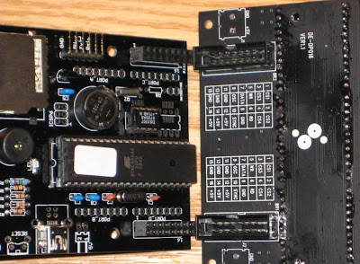
Note: The LED display board has a pair of 2-pin screw terminals on the back (face opposite to LED matrices). They may impede the Dunio644 to plug into the display board. Even if that is not the case (it did not happen to me so far), it is a good idea to extract those screw terminals, which can be useful somewhere else. The picture above shows the LED display board with the screw terminals removed.


Next, copy the two text files, time.txt and quotes.txt onto the SD card, after you made sure the card is formatted as FAT16. For information on how to check the formatting, follow this article on adafruit website.

Open the file time.txt in a text editor and modify the line containing the time. This will be the time used for setting the RTC, and it happens when the clock is powered with the time.txt file on the SD card. (After the time was set, the file is "deleted". See more information here.)

Now, after uploading the sketch to Duino644 board, the text from the file quotes.txt should be scrolling on the top half of the display, and the time should be displayed on the bottom half, as shown in this video.

Congratulations! It is now the time (pun intended :) to design a nice enclosure and to show it off to friends and family.


Related posts:

Thursday, October 29, 2009

Testing Duino644 - RTC and EEPROM

With the Duino644 kit assembled, we can now start testing it.
First, plug the USB cable in the USB miniB onboard connector and make sure the blue LED is lighting.
Alternatively, plug in the FTDI connector (or "FTDI basic breakout"), making sure that the USB (power-only) cable is unplugged. Unlike Wiseduino board, Duino644 is powered by the 5V FTDI pin. Blue LED should be on.


Before uploading any sketch to Duino644, we need to install the Sanguino libraries. (Remember that Duino644 is compatible with Sanguino.) At the end of the integration we will see Sanguino listed in the Tools/Board menu of the Arduino IDE. This is the board that must be selected when working with Duino644.

Before proceeding further, we need to modify boards.txt file, specifically the "Sanguino" section, to look like this:

sanguino.name=Sanguino
sanguino.upload.protocol=stk500
sanguino.upload.maximum_size=63488
sanguino.upload.speed=38400
sanguino.bootloader.low_fuses=0xFF
sanguino.bootloader.high_fuses=0xDC
sanguino.bootloader.extended_fuses=0xFD
sanguino.bootloader.path=atmega644
#sanguino.bootloader.path=atmega644p
sanguino.bootloader.file=ATmegaBOOT_644.hex
#sanguino.bootloader.file=ATmegaBOOT_644P.hex
sanguino.bootloader.unlock_bits=0x3F
sanguino.bootloader.lock_bits=0x0F
sanguino.build.mcu=atmega644
#sanguino.build.mcu=atmega644p
sanguino.build.f_cpu=16000000L
sanguino.build.core=sanguino
sanguino.verbose=false

This is because Duino644 comes with ATmega644 instead of Sanguino's ATmega644P. The difference between the two processors is a second UART in ATmega644P.
(Note: Future revisions may ship with ATmega644P, although the extra functionality is not required nor used in Wise Clock 2.)

Using the FTDI cable, upload the first sketch, the one that sets the real time clock.
(Note: This is just for testing the RTC, since the clock itself can be set using the method described here).

If you feel adventurous you can start directly with the main sketch. It should work, unless you skipped a step or two (forgot to insert the DS1307 chip in the socket, for example) .

Download this file and unzip it in the hardware/libraries folder of your Arduino IDE.
It contains rtc.pde sketch and DS1307 class (header and cpp files).

To set the clock, un-comment the portion of the code in setup(), upload the sketch and run it once. To avoid setting up the same time at every reset and power-up, modify the sketch by commenting out the setup() portion, then upload it again. Now, the board will just send back the time from RTC on serial port.

Testing the EEPROM is done similarly with Wise Clock and detailed here.
(Note: The Wise Clock 2 functionality does not use the EEPROM so far. In the "glass dome" Wise Clock, the quotations were stored in EEPROM, there was no SD card.)

If everything works fine so far, let's take the big jump and load the sketch for Wise Clock 2, which reads the SD card and displays the content of quotes.txt file onto the LED display.

So, next step is the last, and most important, one: uploading the main sketch.

Friday, October 23, 2009

Other "uzes" for Duino644

As mentioned in an earlier post, Duino644 can form the base for an implementation of the Uzebox project. A "uzebox shield" would be plugged in the Duino644 board, much as shields are used with Arduinos. The picture below shows my current effort in trying to get the "uzebox" working. Soldering is done, testing/debugging is next.


A few changes (from the Wise Clock setup) are required:
  • ATmega644 has a different firmware burnt in (not the Arduino/Sanguino bootloader);
  • the microcontroller, nominal frequency of 20MHz, is overclocked at 28.63636 MHz.
Many components on the main board are not necessary (RTC, battery, EEPROM etc). Instead of the LED display (2x8 female header) connectors, the four extension (8 pin female header) connectors are used.

I will post the results of this experiment later. I also plan to design a "uzebox shield" PCB.

On the same note (other uses), it was pointed out by fellow Arduino enthusiast BroHogan, of X10 fame, that the Duino644 is also compatible with his Nex10 board (I am grateful for the link on his page), so it can be used as the base for my next X10 project (following his instructions, obviously).

I will keep you posted on the Nex10 project as well, hopefully I will find the time to do it.

Saturday, October 17, 2009

Duino644 software updates

I was close to giving up on SDuFAT library in favour of FAT16, but my one last attempt worked. I was trying to implement a feature suggested by fellow Arduino blogger BroHogan, to set up the clock using a file on the SD card. Since real time clock is set up quite rarely, this idea makes perfect sense.
Here is how it works:
  • the user creates/copies the file "time.txt", which contains the time, formatted as HH:MM:SS, onto the SD card;
  • after reset, if "time.txt" is found, the clock is set with the given (in the file) time;
  • "time.txt" file is deleted, so the next reset won't find the file anymore;
It is always easier said than done.
Firstly, SDuFAT requires the file to have some characteristics, the most important being to contain a pseudo-EOF (0x03) character.
Secondly, the deletion of the file is not physical, the file does not disappear from the SD card, but it is rather modified so that its first character is the pseudo-EOF (0x03). The "deleted" file can be opened and its content read. The code decides that the file is "deleted" by checking the first character. How smart is that?

setRtcFromSDCard() shown below is the function that gets called in setup().

void setRtcFromSDcard()
{
numSectors = (int) SD.getSectors("time.txt");
if (numSectors == 0)
{
// try again;
delay(500);
numSectors = SD.getSectors("time.txt");
}

if (numSectors == 0)
{
#ifdef _DEBUG_
Serial.println("File time.txt not found.");
#endif

return;
}

// open file time.txt and read its content;
sectorContent = SD.readBytes("time.txt", 0);

// search for the time in the sector buffer;
boolean isTimeFound = false;
for (int i = 0; i<512; i++)
{
if (sectorContent[i] == 0x03)  // EOF
break;

for (int j=0; j<8; j++)
{
timeBuffer[j] = sectorContent[i+j];
}
if (timeBuffer[2] == ':' && timeBuffer[5] == ':')
{
// found the time;
isTimeFound = true;
break;
}
}

if (!isTimeFound)
{
#ifdef _DEBUG_
Serial.println("Could not find time (HH:MM:SS) in file time.txt");
#endif
return;
}

#ifdef _DEBUG_
Serial.print("Time from file is: ");
Serial.println(timeBuffer);
#endif

int hh = 10*(timeBuffer[0]-48) + (timeBuffer[1]-48);
int mm = 10*(timeBuffer[3]-48) + (timeBuffer[4]-48);
int ss = 10*(timeBuffer[6]-48) + (timeBuffer[7]-48);

#ifdef _DEBUG_
Serial.print("RTC time to be set to: ");
Serial.print(hh);
Serial.print(":");
Serial.print(mm);
Serial.print(":");
Serial.println(ss);
#endif

if (hh < 24 && mm < 60 && ss < 60)
{
setTime(hh, mm, ss);
SD.del("time.txt");
}
}


The other software change I made was also the contribution of BroHogan, who wrote (see reply #147) a few functions that perform "fast writes" to the LED display from Sure Electronics. Basically, the calls to digitalWrite() in ht1632_writebits() function have been replaced with calls to fWriteA(). This allows control over the speed of scrolling, ranging from fast to slow, rather than from slow to slower.


Monday, October 12, 2009

New Duino644 kit (revision 1.1)

Thanks for ordering Duino644 kits.
At the moment, all of the "original", revision 1.0 (first batch of) PCBs are gone. In the meantime, I designed an improved version, by adding a few more components, to bring it closer to its intended functionality as the backbone of the Wise Clock:
  • 3 right angle push buttons (for setting up time, snooze, dimming etc);
  • piezo buzzer, for the alarm;
  • bright blue LED, as a background (and power indicator) light;
  • a bit bigger PCB.
This is the schematic for revision 1.1 of Duino644 (download Eagle file here):

and this is the board (download Eagle file here):

To my estimation, I should receive the new PCBs by Oct 20.
Once the new boards are in, I will have to re-price the Duino644 kit to cover the cost of the extra components, essentially increasing it by US$4, to a total of US$58 (free regular shipping to North America) and US$62 (free shipping outside North America) respectively.

The orders placed until then, at the old prices, will be filled with the new design. Consider this as a "promotion" campaign and take advantage of the "reduced" price.

See also:

Friday, September 18, 2009

Buy Duino644 kit


Updated Sep 30, 2011 - DISCONTINUED
This kit is no longer offered. It was replaced by the Wise Clock 3 kit.


Updated Jan 27, 2011
A redesigned (revision 2.1) Duino644 is back in stock. Read more about it here.


Note: Although I added a few more components and I made the board a bit larger, I decided to keep the price unchanged. I hope this is appreciated :)
Also, the picture below won't accurately reflect the actual component set. Missing are the 4 right-angle push buttons (one is replacing the reset button), the micro-speaker and the high brightness blue LED.

I have a few Duino644 kits for sale, on hand and ready to ship. After they are gone, any order will be fulfilled in about 4 weeks time.
Duino644 kits are US$54, with free regular shipping to North America.

For only US$10 more, buy the 2416 LED matrix display from Sure Electronics (ebay), and you can have a nice gadget on your desk to impress your friends an colleagues.

The Duino644 kit includes the following parts:
  • PCB;
  • ATmega644 / 20MHz, with bootloader;
  • either 16 MHz resonator or crystal 16 MHz (plus 2 capacitors 22pF);
  • 40-pin socket for ATmega644;
  • SD card socket (SD card is not included);
  • DS1307 real time clock, either in DIP or SOIC package;
  • 24LC256 EEPROM, either in DIP or SOIC package;
  • 3V coin battery (CR1220 equivalent);
  • battery holder for CR1220;
  • crystal 32,768 Hz;
  • 2 x 16-pin (2x8) female headers;
  • 3 x capacitor 100nF;
  • 78L33 regulator (3V3);
  • 10 x resistor 10K;
  • 3 x resistor 4.7K;
  • micro push button (reset);
  • micro slide switch (power);
  • 6-pin angled male header (FTDI);
  • either USB miniB SMD connector or USB type B connector;
  • infrared receiver;
  • 40-pin female connector;
  • either molex 2-pin angled power connector or JST jack.


Assembling instructions are published here.

Related posts:

Introducing Duino644

Updated Sep 30, 2011 - DISCONTINUED
This kit is no longer available. A very similar kit is the Wise Clock 3.

A simple name from a simple mind: think Arduino clone powered by ATmega644.

Compatible with Arduino software environment (thanks to the Sanguino board, from which it was inspired), Duino644 offers more capabilities than a regular, ATmega328-based Arduino, in the same price range.

Duino644 was originally designed to be used in an advanced new version of Wise Clock. It features the same combo RTC + EEPROM as Wiseduino, and also an SD card socket and connectors for the 24x16 LED matrix display from Sure Electronics.

Duino644 can also be used as a general-purpose Sanguino-compatible board, having all ports (input/ouput pins) exposed and available for use.

Here are some of Duino644 features:

  • PDIP (40 pin) ATmega644 on socket, running at 16 MHz;
  • compatible with Arduino software environment through the addition of Sanguino libraries;
  • directly pluggable into the 2416 LED display from Sure Electronics;
  • semi-pluggable (just one of the two connectors) into the 0832 LED matrix display from Sure Electronics; display type (2416 or 0832) is selectable through jumper;
  • compatible with uzebox game console (requires a different crystal and the "uzebox shield" (under development));
  • relatively easy to solder, with mostly through hole components;
  • on board socket for either SD card or microSD card;
  • on board RTC (DS1307) in either PDIP or SOIC package;
  • on board EEPROM (24LC256) in either PDIP or SOIC package;
  • 6-pin FTDI connector with automatic reset capability;
  • powered, with regulated 5V only, through either standard 2-pin power connector (MLX-WF02R from molex or JST jack from seeedstudio) or USB (type B or miniB connector);
  • power on/off micro switch, easily accessible on the side;
  • available interrupt output pin from RTC;
  • on board backup battery (CR1220), allowing RTC to keep time even when Duino644 is not powered;
  • infrared receiver for remote control;
  • all 4 ports made available through extension headers, spaced at 0.1" multiples, for use with prototype boards;
  • ISCP6 connector for AVR programming.


A few Duino644 PCBs are shown in the photo below.


And this is an assembled Duino644, which is the base for Wise4Sure. With the current software, it works exactly like in this video.


Assembling instructions can be found here.


Creative Commons License
Duino644 by FlorinC is licensed under a Creative Commons Attribution-Share Alike 3.0 Unported License.


References:

Related posts:

Thursday, September 17, 2009

Assembling the "LED matrix shield" kit

Updated May 16, 2011
Fellow Arduino fan Scott graciously offered this PDF version of the assembling instructions.


Updated Feb 17/2010
The content of the "LED matrix shield" kit was slightly changed: the 40-pin female header used as socket for the LED matrix is now replaced with two 12-pin machined female headers, making a much better quality connector, suitable for the thin pins of the LED matrix.
Since these new headers are not as high, the IC sockets, if soldered, would impede on the complete insertion of the LED matrix in the headers; therefore, they have been dropped.

The LED matrix shield for Wise Clock kit includes the following components (also shown in the photo):


Like Wiseduino, the LED matrix shield kit requires some basic soldering skills.
One of the most important aspects of correctly assembling the kit is paying attention to the orientation of the ICs and the LED matrix. The ICs must be positioned to match their notches with those on the silkscreen. Pin 1 (and also Pin 13) of the LED matrix are clearly marked on the silkscreen. To eliminate any doubt I also hand-wrote the pin numbers on the back of the LED matrix.

Following are the steps for assembling the board:
  1. cut the male headers in 4 pieces (two 8 pins, two 6 pins) and solder them in their right places; the easiest way to perform the soldering is to insert the pins into the Arduino extension connectors, like you had a shield in place already;
  2. solder the two 12-pin headers;
  3. solder each 100 ohm resistor after placing it vertically (bend one terminal 180 degrees);
  4. place and solder the 2 push buttons;
  5. solder the remaining 2 resistors, R17 (10K) and R19 (100 ohms);
  6. solder the infrared receiver, then bend it 90 degrees so it becomes parallel to the board and also sticks out a bit;
  7. insert the 3 ICs, matching their notches with those on the silkscreen, then solder them (before inserting them, don't forget to bend their pins, as shown here);
  8. solder the 2 decoupling capacitors (100nF);
  9. carefully insert the LED matrix, paying attention to its orientation (the pin numbers are hand-written on the back, for easier identification).
In the end, the assembled LED matrix shield should look like this (shown plugged into Wiseduino):


The code for Wise Clock can be viewed and downloaded here.

Related posts:

Enclosures - part 3

Since my last posting on enclosures, I have found a few interesting ones that are worth mentioning.

This USB enclosure may qualify as one of the smallest. And here is an update, enclosing an actual circuit board.


Cases in different sizes, from Staples
This particular one (0.55L) fits perfectly the 8x32 LED matrix display from Sure Electronics.


A simple yet practical enclosure


The Chronulator
Not a mere enclosure, but rather a work of art. Check out lots of other Chronulator mods here.


Wednesday, September 16, 2009

Wise Clock sketch

In essence, what the Wise Clock sketch (download from here) does is to display, by scrolling from right to left, two pieces of information:
  • the current time, retrieved from a real time clock (RTC) and
  • a quotation (a one-liner piece of text) retrieved from an external EEPROM.

Some auxiliary functionality offered by the sketch:
  • allows user interaction through a Sony TV remote control and through the "Menu" push button (useful when testing or when the remote is not at hand);
  • displays selectable menu items;
  • sleep mode (turn display off);
  • time could be set through the remote control;
  • uses different colors for display.

Troubleshooting the Wiseduino board

One of the most common problem reported when building an Arduino-clone (not necessarily Wiseduino) is the failure to communicate with the board, that is, the sketch cannot be uploaded.

Here are a few things to check in this case.

- make sure the polarity is correct: the 5V and GND pins in the power connector are indicated in silkscreen;
- measure the current taken by the board; this would give an indication if there is a short somewhere; normally, when only the Wiseduino board is powered (no shields attached), the
consumption should not be higher than 30-50 mA, at most;
- the power switch must have the "lever" towards the female headers to power the board;
- the batteries must be rechargeables (1.2V each, making about 4.8V together); 4 regular AA (new) batteries would provide at least 6V, a bit too much for the ICs;
- make sure the FTDI cable is inserted correctly: ground (black wire) closer to the female headers;
- are the ICs properly inserted into their sockets (so that the notches match, see the photos for assembly instructions)?


A lot more explanations should be provided, no doubt. Your comments, observations, issues are welcome. Also, your contribution to the development and refinement of this code is appreciated.

Related posts:

Buy LED matrix shield kit - DISCONTINUED

Updated Sep 29, 2011
Check out the newest LED matrix shield here.


Updated Sep 1, 2011
As of today, this kit is no longer offered, since I ran out of LED matrices. If you are still interested in the PCBs (because you already have a compatible LED matrix, for example, or maybe you just want to adapt a similar one), drop me a line.


Updated Feb 16/2010
The 40-pin female header, meant as a socket for the LED matrix, was replaced with two 12-pin machined female headers (see this posting), a much better solution. In the same time, since these headers are shorter, the LED matrix will be closer to the board, touching on the ICs underneath. Therefore, I eliminated the 3 IC sockets, since they do not make sense anymore.
Also, the 220 ohms resistor was replaced with a 110 ohms.


Here you can order a kit of the LED matrix shield for Arduino.
Paired with Wiseduino, which has on board RTC (real time clock) DS1307 and EEPROM 24LC256, it makes the Wise Clock.
(Please check out The Shoppe for more kits.)


The LED matrix shield kit includes the following components:
  • PCB, black;
  • 8x8 bi-color (red + green) LED matrix, medium size (47 x 47 mm);
  • 2 x 74HC595 shift registers with 2 x 16 pin sockets;
  • ULN2803A with 18 pin socket;
  • 17 x 110 ohm resistor;
  • 2 x micro push button;
  • 220 ohm resistor;
  • 10K resistor;
  • 2 x 100nF capacitor;
  • 40 pin female header; 2 x 12-pin machined round female header;
  • 40 pin male header;
  • infrared receiver.


Schematic can be downloaded here (Eagle file).


Board layout (download Eagle file here)


Assembling instructions are here.


See related posts:

Tuesday, September 15, 2009

Finally! PCBs galore!

After a long and anxious wait, I finally got the PCBs for Wiseduino and the LED matrix shield.
All outstanding orders will be shipped today.
Thank you all for 3+ weeks of unbelievable patience.


All future orders will be mailed the same day.

Sunday, September 6, 2009

Assembling Duino644

This the schematic (download Eagle file) for Duino644 revision 1.1 (Oct/09)

and the board (download Eagle file):

If you bought the Duino644 kit, you received the following components:
  • PCB with the SD card socket soldered on it;
  • ATmega644 microcontroller and its 40-pin socket;
  • DS1307 real time controller, in either 8-pin DIP (with a socket) or SOIC (surface mounted) package;
  • 24LC256 EEPROM, in either 8-pin DIP (with a socket) or SOIC (surface mounted) package;
  • CR1220 (or equivalent) coin battery;
  • coin battery holder;
  • either a 16MHz crystal and 2 capacitors 22pF, or a 16MHz resonator;
  • crystal 32,768Hz for RTC;
  • 4 right angled push buttons;
  • micro-speaker;
  • high intensity blue LED (SMD, 1206 package);
  • USB miniB-type connector;
  • JSP 2-pin jack;
  • JST 2-pin power connector (with red-black cables soldered);
  • 2 female headers 2x8 pins;
  • 40-pin female header;
  • L78L33 voltage regulator (3V3);
  • infrared receiver IC;
  • 6-pin right angled male header (FTDI connector);
  • 3 decoupling 100nF capacitor;
  • 2x3 pin male header (ICSP connector);
  • 10 resistor 10K;
  • 3 resistor 4K7;
  • resistor 75R.
As with the other kits, soldering the components is not for absolut beginners: this should not be the first kit you assemble. The challenge comes from the few SMD components. Although these are the biggest SMD (surface mounted) packages you will find (SOIC for ICs, 1206 for LED, and the USB miniB), you would still need, depending on your experience, tweezers, de-soldering braid, flux pen.

So here is how we should proceed with the assembling.

1. Solder the USB miniB connector first. Place the connector with its bumps in its holes, so it fits in its place. Then solder the 4 outside extremities to the pads, so it becomes solidly attached to the board. Now solder the 5 pins, with disregard to the bridges that may occur. The next step should be to remove those bridges with the braid.

2. Solder the 75 ohm resistor in its place (R14). This is the current limiting resistor for the LED.

Note: The kit has 3 color-coded resistor values: 10K (brown, black, orange, gold), 4K7 (yellow, purple, black, brown, brown) and 75 ohm (purple, green, black, gold, brown). To simplify identification for those who don't want to consult the color-code chart, use the following photo.


3. Next, solder the SMD LED. The cathode of the LED is marked (green dot, visible through magnifying glass). The cathode is marked on the PCB as well, with 3 dots. Melt some solder on the cathode pad; place the LED's cathode over that pad and solder it; then solder the anode.

4. Time to check that the board gets power from USB, by plugging in the USB cable. The LED should become bright blue. We have ignition!

5. Perform this step if you have the SMD (surface mounted) version of the RTC and/or EEPROM. For best results, moist their pads with a flux pen before you solder them. Avoid using the "de-soldering braid" to remove the eventual bridges, since these are temperature sensitive, unlike the USB connector soldered earlier. (Pay attention to the orientation of these chips: the dots marking pin 1 must be closer to the bottom of the PCB.)

6. Solder the 4K7 resistors (yellow, purple, black, brown, brown), R5, R6 and R7. Then continue with the remaining resistors, all 10K.

7. Solder the IC sockets, for ATmega644, RTC and EEPROM (if the last two were provided). Pay attention to their orientation, so that their notches match the notch in the silkscreen (this is not vital, but it will help later to correctly place the ICs).

8. Solder the two crystals (16MHz and 32768Hz), then the capacitors (C1 and C2 are 22pF, the rest are 100nF). The 16MHz (bigger) crystal goes in the three-hole spot (center is not used) close to the pins 11-13 of the microcontroller. Latest PCB version has this spot marked "XTAL".

9. Solder the battery holder. (I personally cut the 3 bumps underneath, so it gets closer to the board.). Then solder the ISCP (optional) and FTDI connectors.

10. Solder the 4 right-angle push buttons, the micro-speaker and the JSP (power) jack. Continue with soldering the 2 LED display connectors (2x8 female headers).

11. Solder the 3V3 regulator after placing it to match the silkscreen.

12. Insert the ATmega644 chip in its socket, then the RTC and the EEPROM (if you have the DIP version). Pay attention to their orientation, by matching the notches on the IC with the notches in the socket (if they were placed correctly in step 7 :) Also, remember to bend their pins just a tiny bit, on a hard surface (e.g. desk) to make them parallel, as so nicely documented in many of ladyada's instructionals (including this one).

13. Optionally, solder the infrared receiver. (This part should be visible to the remote control. Therefore, its final place will be dictated by the enclosure. Depending on that, it may be necessary for the infrared receiver to be "extended" with some wires.)
Pay attention to its orientation: when inserted, the bump should be facing inwards, toward the board. To be visible by the remote control, the IR receiver should also stick out from behind the LED display, so it would need to be bent 90 degrees, as shown in the photo below.

It has been suggested (thanks Mowcius) that a 3-pin female header can be soldered in place of the IR receiver. This will act as a socket, eliminating the risk of soldering the part wrongly, as it happened in a few instances. More, it will allow for the cables to be unplugged when the device need to be dis-assembled (assuming that the IR receiver is fixed to the enclosure).


At this point, Duino644 is assembled and ready for testing (continue here).
It should look pretty close to the one below (which is missing a few non-essential parts).

Saturday, September 5, 2009

Wise Clock 2 (Duino644-based) user manual

A user manual for Wise Clock is long overdue. I myself need to look through the code in order to find out what the commands are and how they work.

This "manual" is for Wise Clock 2, the one based on Duino644. It has extended functionality over Wise Clock ("glass domed"), since it is based on a more powerful processor and "platform" (featuring SD card, speaker, more buttons etc).

It will be long until this post becomes a proper manual, and hopefully I will find the time to update it regularly, as the features evolve, get refined (or dropped :) etc.

I should start by stating that the main feature of the Wise Clock 2 is to display the time, along with a user-defined scrolling text. The text is usually quotations (wisdom by famous people, funny punches, philosophic one-liners, sayings, maxims etc) gathered in the file named quotes.txt on the SD card. This file can be edited by anyone, on a PC.

Another feature that makes Wise Clock 2 original is the display: relatively large LED matrix, with a 16x24 resolution, readable from a considerable distance. Scrolling, at user-defined variable speed, enables even long text messages to be displayed in an effective manner and read easily.

Although some of the features may not be implemented yet, I think it is good to have them enumerated as requirements, so they are not forgotten :)

Commands

User command are issued through either the on-board buttons or through the Sony TV remote control (using Sony-standard infrared signals).

1. Remote control
  • CH+
  • CH-
  • VOL+
  • VOL-
  • digits
  • Enter
  • Power On/Off

2. Menu button
  • access the menu list at any time;
3. Set button
  • select a menu item from the menu list;
  • increase scrolling speed at any time;
  • set time for alarm, when in the right menu item;
  • set alarm on/off, when in the right menu item;
4. + button
  • increase display brightness at any time;
  • browse through the menu items;
  • increase speaker volume when in the right menu item;

Configuration

Time can also (besides the buttons) be set using the SD card time.txt file, featured presented here.

There is a default scrolling speed and a default display brightness.

Other configuration parameters can be set through a configuration file on the SD card.