Saturday, March 13, 2010

BookClock - new member of the Wise Clock family


Don't throw away that carboard box your Monochron was packaged in. You can use it as enclosure for the cheapest (yet) member of the Wise Clock family, currently named "BookClock" (for the reason that it can be placed on a book shelf, among books).

Note: The featured cardboard box is sold by ULine. It has the code ULine S-974 and can be found here.

The BookClock contains only two elements: Wiseduino, of course, and the 8x32 LED display from Sure Electronics. One nifty addition is a tilt sensor that changes what is displayed depending on the clock orientation (standing on the smallest side as a book, or laying flat on the largest side).


To build it, let's start with the enclosure, the cardboard box. With an xacto knife, cut an opening for the display.


The opening, waiting for the display, should look like this:


Stick some scotch tape along the cut lines to strengthen (and also smooth) them.
After inserting the display, attach it to the box with some sticky tape (I used electrical tape).
This is how it looks when standing, as a book on the shelf.


The "guts" of the BookClock is a "hacked" Wiseduino board, which looks like this:


This board does not have the extension (female) headers, since there will be no shield mounted anyway. So I soldered (the required wires of) the 16-wire ribbon cable directly where the headers would have been.

Wires number 15 and 16 of the ribbon are GND and Vcc (5V) respectively. For mechanical reasons I soldered them into D0 and D1, whose lines were previously cut. (I then re-connected D0 and D1 to Vcc and GND respectively, see the red and blue wires.)

The board also has a tilt sensor soldered between analog 0 (A0) and ground. A 10K resistor pulls A0 up (connects it to Vcc).

This is how it looks on the inside (not yet connected to power).

Thursday, February 18, 2010

Memory mapping in 16x24 LED displays from Sure Electronics

When Sure Electronics released their green version of the 16x24 LED display, I was surprised to notice that this display was not compatible with the red one. One could not just unplug the red display and replace it with the green one and expect it to work. I found out about this the hard way. After a bit of confusion (I thought that my green display was defective), it was pointed out to me that the datasheets for the two displays are different. It took a little effort to accommodate the green display in the Wise Clock 2 software. Essentially, I had to adapt the function ht1632_plot to work with the new display.

I show below some diagrams representing the memory mapping for the two displays.
The datasheets (red here, green here) do not explain this mapping very clearly. I thought my drawings may bring some better understanding to others as well.


Friday, February 12, 2010

Assembling the "Dual Bi-color LED matrix shield" kit

This kit contains the following parts:
  • PCB (compatible with Arduino shields);
  • two 8x8 bi-color bright LED matrices (side is 47mm or 1 7/8" in length, 5mm LEDs);
  • 4 x 74HC595 shift registers;
  • ULN2803 transistor array;
  • 4 x 16-pin IC socket;
  • 32 current-limiting resistors;
  • 4 x 100nF decoupling capacitors (color may vary);
  • 4 x 12-pin machined female headers;
  • 40-pin male header;
  • rotary encoder with push button and knob.

To assemble the kit, follow the step-by-step process below.
  1. insert the four 16-pin IC sockets, making sure that their notches match those in the silkscreen; their orientation is important (errors are not fatal though), since it will indicate the orientation of the ICs which will be later plugged into them; solder the sockets, making sure that they are close to (touching) the board;


  2. cut the 40-pin male header in 4 pieces, two 8-pin and two 6-pin, then solder them in their corresponding places; these are the pins which will plug into Arduino's (female) extension headers; as always with the shields, it is advisable to have them plugged into the Arduino extension connectors while soldering them to the shield;


  3. solder the four 12-pin female headers; these are the connectors for the LED matrices;


  4. solder each resistor after placing it vertically (bend one terminal 180 degrees);


  5. solder the decoupling capacitors;


  6. place the ULN2803 chip, paying attention to its orientation (notch on chip must match notch on silkscreen) and solder it;
  7. carefully insert the integrated circuits into their respective sockets, matching the notches (socket-chip); to make sure they can be inserted, bend the pins on both sides just a tad (as shown here, courtesy of adafruit), so they become parallel;


  8. insert the LED matrices, paying attention to their orientation: pin 1 of the matrix must match pin 1 on the board (the pin numbers are hand-written by me on the back).


    The assembled shield should look like the one below.


    Related posts:

Thursday, February 11, 2010

Wiseduino and XBee

This is a long-overdue piece of documentation, which I started many months ago and never had a chance to finish. It may not be totally complete even now, but at least it gives some direction towards the integration of the XBee radio and Wiseduino.

One of the features of Wiseduino is the ability to plug in an XBee adapter from adafruit, in the designated 10-pin female header (provided in the Wiseduino kit). The intention is for this header to be soldered on the back of the board, as shown in this photo:


The XBee adapter should be plugged in as shown in the following photo:


Beside the wireless communication, the XBee adapter provides a few more services:
  • remote sketch upload;
  • 3V3 for the main board, usable by other shields (about 50 mA worth);

In order to use it with Wiseduino as in the setup shown above, the XBee adapter requires a few little modifications.

1. The first is a trace cut, as pictured below:


Basically, the two extreme holes for the header are connected together, and to 3V3. We are going to use one of these redundant connections for our purposes, and that is to access XBee's pin D3 from the Wiseduino board (as explained in adafruit's XBee tutorial).

2. Secondly, the straight header (provided in adafruit's kit) must be soldered perpendicular to the board.

3. Thirdly, a wire needs to be soldered between D3 and the extreme left pin of the header (the one that was isolated at step 1 by cutting the trace).


Before inserting the XBee radio module, the adapter should look like in the photo below.


After the hacks are done, for the remote sketch upload, just follow adafruit's great tutorial.
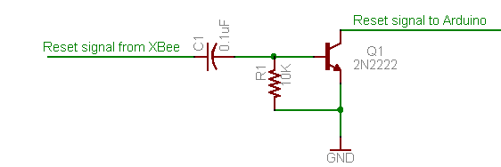
Notice that the small circuit with the transistor in the mentioned tutorial is already implemented on the Wiseduino board.

Related posts:

Tuesday, February 9, 2010

"Finished" Wise Clock 2 with Duino644

By "finished" I am only referring to the enclosure, not to the evolving (hopefully) software. Once released to the open source community, the software should be, in theory, never "finished", like a piece of art :)

Here is a photo of a simple (and cost-effective), yet elegant, enclosure, consisting in two laser-cut sheets of 1/8" plexiglass separated by plastic spacers.