Sunday, May 8, 2011

Spilling the beans - C3Jr

I don't usually do this: advertising a project before its completion. But the beans are out anyway :)

I have already received inquiries about ClockTHREE price and availability. Although I don't make this kit and I did not participate in its design, I would gladly redirect all questions to its makers, the WyoLum team, mainly Justin and Anool.

The latest news is that ClockTHREE (read my brief review here) is already available in their store as a "complete kit" for US$333. It may look expensive, but considering what is included, it may actually pass as a bargain. Just think of the following:
  • stylish, unique, wall-mountable, well designed & engineered, hackable, Arduino-programmable, multi-color Word Clock, featuring alarm, day-of-week and temperature display, scrolling text, plus many function modes;
  • 160 high-quality 10mm RGB diffused LEDs and 32 10mm diffused white LEDs;
  • a huge (about 25cm x 30cm) PCB and a lot of electronic components, including an ATmega328 and a ChronoDot;
  • a large set of laser-cut plastic parts for baffles and enclosure, and the laser printed faceplates;
  • great (open source) software developed specifically for it.

The assembled ClockTHREE is also available for US$444 (they surely have an affinity for numbers :).

Now back to the beans: a simplified, and hence lower-cost, version of ClockTHREE is under development by the same great WyoLum team (I also joined in for this one). It was named C3Jr, as in ClockTHREE Junior. Its functionality will be similar: word clock, alarm, day of week, various display modes etc. C3Jr will be single-color (usually white; blue is also considered), just a bit smaller, and, hopefully, as elegant as its predecessor. The "C3Jr complete kit" will be priced at under $200 and available mid June (2011), just in time for MakerFaire North Carolina.

Stay tuned for more details.


Updated May 16, 2011
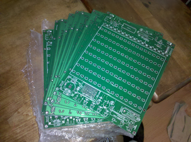
PCBs are in, shown below (photo by Justin).


Updated May 20, 2011
C3Jr assembled by Justin. I think it looks beautiful.


Tuesday, May 3, 2011

ClockTHREE completed!

My previous post on ClockTHREE, a while back, was about my first impressions. The work I did then, starting to assemble the clock, consisted in a lot of tedious soldering and did not require a lot of thinking and analysis. Yet, not surprisingly, the clock passed all the software tests.

Now that I received the long-awaited blue LEDs, standoffs and faceplates (thanks again Justin), I was able to finalize my ClockTHREE. And let me tell you something: this is the most under-rated Arduino-based project in the history of Arduino, seriously. I am just now impressed with the amount of work that went into this project, from designing the PCB, to writing the scripts to generate the faceplates, to developing the software/firmware. I did a few of my own and I know what goes into this kind of endeavors. ClockTHREE is one complex piece of engineering: electronics, mechanical structure, software.

Here are a few more observations:
  • the top frame fits perfectly on top of the baffles (the inside baffles being a tad taller, to compensate for the thickness of the frame), holding them down and keeping them square (as shown in the next two photos);


Frame on top of the baffles:


  • everything (top and bottom covers, faceplate, baffles and frame, board) is held solidly in place with just 6 sets of hardware (standoff, screws, washers);
  • the software works impeccably right off the bat (I was going to set the RTC time using an older library, then I found the operating instructions);
  • the software has quite a few features implemented already (e.g. setting the display color, few display modes etc);
  • the visual aspect of the clock is as elegant as that of QlockTWO.


Justin and Anool did an impressive job on ClockTHREE. Come to mind Steve Wozniak's words: "I would have loved to have invented that".

Saturday, April 30, 2011

My Geiger counters

I have had a Geiger counter project on my "todo" list for a long time, ever since fellow Arduino hobbyist BroHogan (aka John) created one  more than a year ago. His Geiger project received a lot of interest lately, with the unfortunate events in Japan, so he decided to provide a kit (which seems, not surprisingly, to be sold out pretty quickly). John graciously offered to send me one of his kits, which I just finished assembling, and I am glad to report on the impressions and results.

First of all, DIYGeigerCounter is a big kit in a small package; it's got more than 40 through-hole parts, on a PCB that would fit in an Altoids gum tin box (Note: only the PCB, not the Geiger sensor itself, which is too long).


The kit contains both the Geiger analog circuit (that generates the high voltage for the tube) and the ATmega328 microcontroller part (that can eventually drive an LCD), together on the same board.

The version I received is 1.0; the version John is selling is 1.4. The differences are minor: the latest revision has the resistors placed horizontally, a few more headers on the processor side and four screw holes in the corners.

Because of the complexity of the circuit, one needs to take the time to read the assembling instructions. There are lots of resistors and capacitors that need to be placed correctly. And then there are the diodes. To determine their orientations (they are not marked on the silkscreen in revision 1.0), one needs to use the continuity meter and the schematic, which is not a bad thing at all, since one learns about the circuit. (I know that the tendency is to just assemble everything in a haste, because I do that myself. I only learn when something goes wrong and the circuit does not work. Then I have to go to the schematic and use the multimeter.) OK, so no shortcuts here; this kit requires a bit of study, checking and identifying the parts, even crossing them off the list once installed (this is what I did).

Needless to say that the kit worked superbly right off the bat. I measured (with a regular voltmeter, not using the method BroHogan describes here) the high voltage, and it is 310V. It may sound dangerous, but I felt nothing when I touched those pads. The assembled Geiger counter is shown below, without the Geiger tube.


Notice the nice clips for the tube. Other kits usually recommend just wrapping some wire around the tube's terminals, or worst, soldering the wires directly to the tube (this procedure may damage the tube, apparently).

The tube I used for partial testing (since I don't have any radioactive materials just yet) was part of another, much simpler (and much more expensive) kit, from electronic goldmine, shown assembled below.


I just inserted the clips over the installed tube and powered DIYGeigerCounter and started clicking (with the LED turning on) every 2 seconds, giving thus a "reading" of about 30 CPM (clicks per minute).

Next step is the addition of the LCD, detailed here. Then, I will need to build and enclosure, so I can take it out on the field and impress my friends when they chose their granite kitchen counter-tops :)

Saturday, April 23, 2011

Scrolling message sign display with Wise Clock 3

A feature of Wise Clock 3 board that was not previously "advertised" is its ability to drive more than one 3216 LED display, making it easy for anyone to quickly assemble a window sign display.

Wise Clock 3 board plugs into both connectors of the display. To cascade a second display, you will need to solder, on the Wise Clock 3 board, a right-angle 16-pin (8x2) male header in the place provided below the existing connector, then use the 16-wire ribbon cable coming with the 3216 display to connect this newly added header to the input connector of the second 3216 display, as shown in the photo below.


A demo (put together by Tim Gilmore) of a 64x16 windows sign display powered by Wise Clock 3 is shown in action in the following video. The demo software can be downloaded from here (for more details see this thread in the arduino forum).


Besides saving more, making your own clock brings a great sense of accomplishment.


Related posts:

Tuesday, April 19, 2011

A new kind of baffles

It started as a challenge, then it became an obsession: the baffles for my own version (still work in progress) of Word Clock, the grid that separates the LEDs from one another, so that every letter on top of a LED can be lit individually.

Baffles for Word Clock clones have been made before, see here and here (part of this and that instructables, respectively). These examples separate groups of LEDs rather than each individual LED. Justin and Anool of ClockTHREE fame raised the bar (they did not call it ClockTHREE for nothing :) with their individually addressable LEDs and the associated baffles, an elegant and remarkable solution, nicely integrated with the board and the case. Trying to replicate their results for just one prototype is both expensive (laser-cutting) and tedious (calculations, drawings, assembly). After a lot of thinking, I "invented" my own solution for the baffles, as shown in the photo below.


Basically, I used 40-pin female headers to separate the low-profile, wide-angle, LEDs. The headers are held in place by soldering them to the prototyping board. For the 8x14 LED matrix, I used about 40 headers, for a cost of about $12.


Generally speaking, designing and making the baffles is a feat. With so many choices, one needs to answer a few questions before designing them:
  • what material should be used (cardboard, plastic, wood etc)?
  • what manufacturing process would be the most appropriate (in terms of price, assembly time etc)?
  • how could they be attached to the board?

Plastic is an obvious choice for the material:
  • laser-cut (expensive, requires the assembly of the parts);
  • mold-injected (perfect for mass-production; no assembly required: what you get is what you use);
  • 3D printed (suitable only for prototyping; may be expensive).

Even after having the baffles made, the question of how to attach them to the board still remains. They need to be placed equidistant between the LEDs and held solidly in place (screwed down to the board maybe?).

Now you don't need to wonder anymore why Peggy 2 does not come with baffles :)