The main reason I called one of my latest device "ugly" in a recent post was because I could not meet this requirement (well, I did not design the whole thing either). Essentially, that particular Geiger counter is very difficult to fix. Accessing to the FTDI header to re-program the Arduino Mini is also challenging. If, for some reason, the LiPo charger breaks down, the replacement miniature board would require drilling, then trace-cutting, then some wires to be soldered to the traces. I would rather throw it away then go through the (still undocumented) exercise again.
Considering all of the above, I designed a Geiger counter board shaped and dimensioned as the original Arduino, so it can fit in the Arduino enclosure from Adafruit, together with the 16x2 LCD display. The schematic is based on BroHogan's DIYGeigerCounter, to which I added the LiPo charger (with USB miniB socket) and a toggle switch for power on/off.

It does not get much simpler than this. The Geiger counter board is screwed to the half case, together with the display. With the case closed, the "free-floating" Geiger tube and the LiPo battery are held in place pretty well without additional fasteners, just by being pressed against each other.
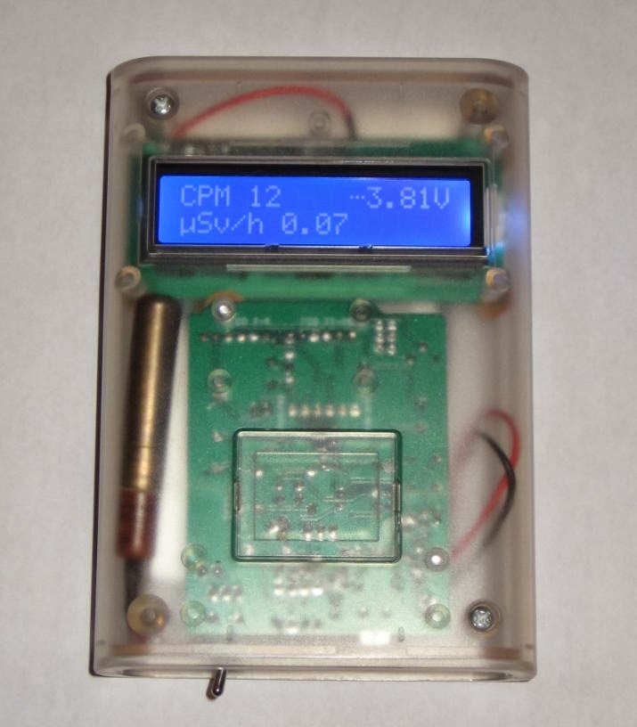
There are 2 LEDs soldered to the bottom side of the PCB: one indicates LiPo charging, the other is the radiation indicator. This being another reason the enclosure needs to be transparent or translucent (it's not only for showing off the simple yet elegant internals :).
The 3V3 LCD display is connected to the board with a pair of 6-wire ribbon cable which can be easily unplugged if necessary. Sketches are uploaded to the ATmega328 (SMD) through the 6-pin FTDI connector, from Arduino IDE (as a matter of fact, I uploaded the release 10.2 of the DIYGeigerCounter software by BroHogan).
There is enough room in the enclosure to fit a second SI-29 Geiger tube in parallel (electrically) with the existing one, for better sensitivity.
The counter works perfectly with the bigger SBM-20 tube as well, but it is a bit challenging to fit that inside without some compromises.
The bottom cover of the enclosure does not require any modification (e.g. filing, drilling); one opening is still used for the (now smaller) USB connector, the other (originally designed for the power jack) is re-purposed for the power toggle switch.

Note that the miniB USB connector is only used for charging the battery and not for uploading sketches or for USB serial communication.
It would be very nice if this stylish enclosure gets re-designed for the 128x64 OLED display.


No comments:
Post a Comment