From the datasheet, the HDSP-253x looks like the LED dot-matrix equivalent of an HD44780-controlled LCD display:
- data is sent on a 8-bit bus;
- ability to decode 128 ASCII characters, which are permanently stored in ROM;
- allows definition of 16 user-programmable symbols that are stored in the on-board RAM.
I wired the display to an ATmega328 (internal oscillator at 8MHz) through a 595 shift register, using the schematic in this post from nycresistor blog.

They use the HDSP-2111 display, which is very similar to the HDSP-2534 I have. They also provide demo source code for writing data to the display. Needless to say everything works as described. My contribution to the code is a function that sets the display brightness at one of the predefined 7 levels.

As shown in the photo above, all components fit on a 5cm x 7cm prototype board. The RTC is DS1307 with backup battery. The hours and the minutes can be set from the two buttons.
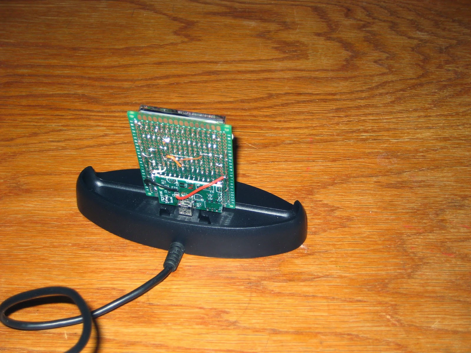
The easiest solution to "finish" the clock was to mount it on a phone dock charger I had around (which can be also found on ebay for $3 or so). Plugging the clock board into the dock's USB connector requires a "breakout" miniB (like this one sold by adafruit). I improvised one by cannibalizing a Geiger PCB, as shown in the photo below.

The "breakout" miniB connector is attached to the back of the clock board by soldering a few header pins in matching holes of the 2 boards. The assembly is mechanically solid.

The current draw at the lowest brightness (which is still very visible, as shown in the photo above) is between 20 and 40mA. At the highest brightness, the clock draws about 200mA.
Future improvements may include a Bluetooth module to display messages sent from a smart phone. And of course, designing a proper PCB :)
Update (Jul 20, 2014): A kit for this clock is now available.


Hi, this is the first I've seen someone else using the HDSP displays with an Arduino, or AtMega, I spent ages creating something which is almost identical to your clock here and never managed to get the brightness adjustment to work. i can send you a picture if you are interested, it is still on breadboard, but has been working for about 6 months. I would be very interested in seeing your code to see how to control the brightness? Is that possible?
ReplyDeleteCheers Guido
Hey Guido,
DeleteHere is the code, which should really be in github (I'm just afraid of the learning curve for now):
/*
Demo Code for HDSP 2111 using SN74LS595N
Matt Joyce < matt@nycresistor.com >
Mark Tabry
(FlorinC, May 2, 2014) adapted for HDSP-253x.
*/
#include
#include "digitalWriteFast.h"
#include
#include "DS1307.h"
// used to enable/disable Serial.print, time-consuming operation;
// to minimize the code size, all references to Serial should be commented out;
//#define _DEBUG_
// display brightness definitions, indicating percentage brightness;
#define HDSP253X_BRIGHT_100 0x00
#define HDSP253X_BRIGHT_80 0x01
#define HDSP253X_BRIGHT_53 0x02
#define HDSP253X_BRIGHT_40 0x03
#define HDSP253X_BRIGHT_27 0x04
#define HDSP253X_BRIGHT_20 0x05
#define HDSP253X_BRIGHT_13 0x06
#define HDSP253X_BRIGHT_0 0x07
//Pin connected to latch pin (ST_CP) of 74HC595
const int latchPin = 8;
//Pin connected to clock pin (SH_CP) of 74HC595
const int clockPin = 12;
////Pin connected to Data in (DS) of 74HC595
const int dataPin = 11;
const int ce = 5;
const int wr = 6;
const int a2 = 4;
const int a1 = 3;
const int a0 = 2;
const int rst = 10; // REM: not connected; instead, D1 is connected to RST (!?)
const int a3 = 9;
#define PIN_BTN_SETHOUR 15
#define PIN_BTN_SETMIN 16
// globals; their values get set by calling getTimeFromRTC();
int hour;
int minute;
int second = 0;
int year, month, day;
// read time from DS1307 at intervals;
#define MAX_TIME_READING_COUNTER 1000
long timeReadingCounter = MAX_TIME_READING_COUNTER;
char displayBuffer[8];
void setup()
{
#ifdef _DEBUG_
Serial.begin(9600);
Serial.println("in setup");
#endif
//set pins to output because they are addressed in the main loop
pinMode(latchPin, OUTPUT);
pinMode(dataPin, OUTPUT);
pinMode(clockPin, OUTPUT);
pinMode(a0, OUTPUT);
pinMode(a1, OUTPUT);
pinMode(a2, OUTPUT);
pinMode(a3, OUTPUT);
pinMode(rst, OUTPUT);
pinMode(ce, OUTPUT);
pinMode(wr, OUTPUT);
digitalWrite(ce, HIGH);
digitalWrite(wr, HIGH);
resetDisplay();
// buttons to set hours and minutes are on A1 (D15) and A2(D16) respectively;
pinMode(PIN_BTN_SETHOUR, INPUT);
pinMode(PIN_BTN_SETMIN, INPUT);
setBrightness(HDSP253X_BRIGHT_13);
setTime(16, 2, 0);
}
void resetDisplay()
{
digitalWrite(rst, LOW);
delayMicroseconds(1);
digitalWrite(rst,HIGH);
delayMicroseconds(150);
digitalWrite(a3, HIGH);
}
void writeDisplay(char *input)
{
#ifdef _DEBUG_
Serial.println(input);
#endif
for (int i=0; i<8; i++)
{
digitalWriteFast(a0, (1&i)!=0?HIGH:LOW);
digitalWriteFast(a1, (2&i)!=0?HIGH:LOW);
digitalWriteFast(a2, (4&i)!=0?HIGH:LOW);
digitalWriteFast(ce, LOW);
// write data to the bus;
digitalWriteFast(latchPin, LOW);
shiftOut(dataPin, clockPin, MSBFIRST, input[i] );
digitalWriteFast(latchPin, HIGH);
digitalWriteFast(wr, LOW);
digitalWriteFast(wr, HIGH);
digitalWriteFast(ce, HIGH);
}
}
void writeChar(int pos, char c)
{
digitalWriteFast(a0, (1&pos)!=0?HIGH:LOW);
digitalWriteFast(a1, (2&pos)!=0?HIGH:LOW);
digitalWriteFast(a2, (4&pos)!=0?HIGH:LOW);
digitalWriteFast(ce, LOW);
// write data to the bus;
digitalWriteFast(latchPin, LOW);
shiftOut(dataPin, clockPin, MSBFIRST, c );
digitalWriteFast(latchPin, HIGH);
delay(10);
digitalWriteFast(wr, LOW);
digitalWriteFast(wr, HIGH);
digitalWriteFast(ce, HIGH);
}
void scrollDisplay(char *words)
{
char buffer[9];
int i = 0;
while(words[i] != 0)
{
boolean blank = false;
for (int j = 0; j<8; j++)
{
if ( !blank && words[i+j] == 0 )
{
blank = true;
}
if ( blank )
{
buffer[j] = ' ';
}
else
{
buffer[j] = words[i+j];
}
}
buffer[8]=0;
writeDisplay(buffer);
delay(200);
i++;
}
}
(continuation of the above....)
Deletevoid loop()
{
checkButtons();
timeReadingCounter++;
if (timeReadingCounter > MAX_TIME_READING_COUNTER)
{
getTimeFromRTC();
sprintf(displayBuffer, "%02d.%02d.%02d", hour, minute, second);
writeDisplay(displayBuffer);
timeReadingCounter = 0;
}
}
void getTimeFromRTC()
{
int rtc[7];
RTC_DS1307.get(rtc, true);
// check to avoid glitches;
if (rtc[DS1307_MIN] < 60 && rtc[DS1307_HR] < 24 && rtc[DS1307_SEC] < 60)
{
second = rtc[DS1307_SEC];
minute = rtc[DS1307_MIN];
hour = rtc[DS1307_HR];
}
// check to avoid glitches;
if (rtc[DS1307_YR] <= 2050 && rtc[DS1307_MTH] <= 12 && rtc[DS1307_DATE] <= 31)
{
day = rtc[DS1307_DATE];
month = rtc[DS1307_MTH];
year = rtc[DS1307_YR];
}
#ifdef _DEBUG_
Serial.print("Time is ");
Serial.print(rtc[DS1307_HR]);
Serial.print(":");
Serial.print(rtc[DS1307_MIN]);
Serial.print(":");
Serial.println(rtc[DS1307_SEC]);
/*
Serial.print("Date is ");
Serial.print(rtc[DS1307_YR]);
Serial.print("/");
Serial.print(rtc[DS1307_MTH]);
Serial.print("/");
Serial.println(rtc[DS1307_DATE]);
*/
#endif
}
void setTime(int hh, int mm, int ss)
{
getTimeFromRTC();
// NOTE: when setting, year is 2 digits; when reading, year is 4 digits;
RTC_DS1307.stop();
RTC_DS1307.set(DS1307_SEC, ss);
RTC_DS1307.set(DS1307_MIN, mm);
RTC_DS1307.set(DS1307_HR, hh);
RTC_DS1307.set(DS1307_DOW, 1);
RTC_DS1307.set(DS1307_DATE, day);
RTC_DS1307.set(DS1307_MTH, month);
RTC_DS1307.set(DS1307_YR, year > 2000? year-2000 : year);
RTC_DS1307.start();
}
void setDate(int newyear, int newmonth, int newday, int dow=1)
{
getTimeFromRTC();
// NOTE: when setting, year is 2 digits; when reading, year is 4 digits;
RTC_DS1307.stop();
RTC_DS1307.set(DS1307_SEC, second);
RTC_DS1307.set(DS1307_MIN, minute);
RTC_DS1307.set(DS1307_HR, hour);
RTC_DS1307.set(DS1307_DATE, newday);
RTC_DS1307.set(DS1307_MTH, newmonth);
RTC_DS1307.set(DS1307_YR, newyear);
RTC_DS1307.set(DS1307_DOW, dow);
RTC_DS1307.start();
}
void checkButtons()
{
// increment hours and minutes;
if (LOW == digitalRead(PIN_BTN_SETHOUR))
{
hour++;
if (hour>23) hour = 0;
setTime(hour, minute, 0);
delay(400);
}
if (LOW == digitalRead(PIN_BTN_SETMIN))
{
minute++;
if (minute > 59) minute = 0;
setTime(hour, minute, 0);
delay(400);
}
}
void setBrightness(uint8_t brightness)
{
digitalWrite(a3, LOW);
digitalWrite(latchPin, LOW);
shiftOut(dataPin, clockPin, MSBFIRST, brightness );
digitalWrite(latchPin, HIGH);
delay(20);
digitalWrite(ce, LOW);
delay(20);
digitalWrite(wr, LOW);
delay(20);
digitalWrite(wr, HIGH);
delay(20);
digitalWrite(ce, HIGH);
delay(20);
digitalWrite(a3, HIGH);
}
Sorry about that, maybe one of these days I will push myself to do it.
DeletePlease let me know how it works for you. If you have a link to your post, please post it here as well.
DeleteHi Florin, I was getting a bit confused I think. The Brightness definitions is what I was looking for, hopefully I'll get an opportunity to try it soon. I will be using an LDR on an analogue pin to set the brightness determined by ambient light level.
ReplyDeleteI'm trying to find lots of uses for these displays as I have 8 of them and a box full of DLG7137 displays I'm trying to find a use for too :-)
Thanks for this I'm sure it will be of great help.
I don't have a post for my clock, but I could send a couple of pics if you wish.
Guido
Thanks you are a genius! that worked perfectly. I added your brightness definitions to my code then used an LDR to determine the brightness of the display.
ReplyDeleteThanks :)
DeleteI'm glad I could help.
I have plenty of those hdsp displays, I'm good with hardware electronics but when comes to programming I don't understand any of it, iv tried copying this code but arduino wouldn't compile, I assume there's parts of code missing? Like those two blank "#incude" and do I need some specialised custom written libraries? Iv been attempting to randomly do stuff to this code for months but nothing works, please help. Would be shame to waist box of those hdsp displays.
ReplyDelete