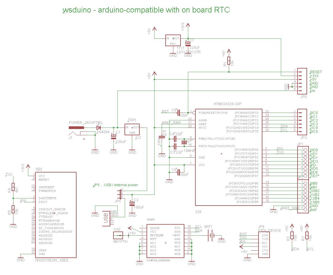
I redesigned wsduino mainly for the Axiris IV3 clock, whose enclosure allows for only 2 boards (Arduino + IV3 shield), with openings for power socket, USB, and no accessible buttons. Essentially, wsduino saves you an extra shield, which would have hosted the RTC (+backup battery) and the XBee.
wsduino is now available as a kit, as shown in the photo below.

The wsduino kit includes:
- PCB
- ATmega328 processor with bootloader
- 28-pin socket
- 16MHz crystal
- 2 x 22pF capacitor
- power jack
- 7805 voltage regulator
- 1N4001 diode
- USB miniB socket
- DS3231 RTC (SMD)
- A1117 3V3 regulator (SMD)
- CR1220 battery + holder
- 4 x 10k resistor
- 4k7 resistor
- 3 x 100nF capacitor
- 47uF/25V capacitor
- 47uF/16V capacitor
- 470uF/10V capacitor
- 2 x 10-pin 2mm female header for XBee
- 40-pin 0.1" female header
- 3-pin header + jumper (selection of power source)
An FTDI breakout is required to upload sketches.
Although the assembly is quite trivial, I enumerate below the steps, for the detail-oriented :)
- solder the DS3231 SMD chip on the bottom of the PCB, making sure the chip orientation is correct;
- solder the A1117 chip, also on the bottom of the PCB;
- solder the resistors R1-R4 (their values are shown in silkscreen);
- solder the IC socket, with the correct orientation of the notch; then insert the ATmega328 chip (after you bent the two sides of pins on a flat surface, one side at a time, to become parallel);
- solder the crystal (orientation does not matter)
- solder the USB miniB socket;
- solder the 7805 voltage regulator to match its shape in silkscreen;
- solder the ceramic capacitors (orientation does not matter);
- solder the 3 electrolytic capacitors, paying attention to their orientation;
- solder the diode, also paying attention to its orientation;
- solder the power jack;
- solder the 2 XBee headers;
- cut, then solder, the extension headers;
- solder the battery holder, then insert the battery.

Here are some photos of the assembled board.

The RTC (DS3231) and 3V3 voltage regulator are soldered on the bottom.

Perfect Arduino-compatible to quickly build a clock. Just add a display shield :)


No comments:
Post a Comment