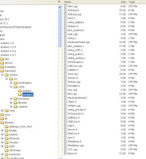
The Wise Clock 4 files are all in the same "TheClock" folder, directly under "libraries", as shown in the following screenshot.
But before uploading to ATmega1284, this section needs to be inserted in boards.txt (*):
##############################################
atmega1284.name=Sanguino W/ ATmega1284p 16mhz
atmega1284.upload.tool=avrdude
atmega1284.upload.protocol=stk500v1
atmega1284.upload.maximum_size=129024
atmega1284.upload.speed=57600
atmega1284.bootloader.low_fuses=0xFF
atmega1284.bootloader.high_fuses=0x98
atmega1284.bootloader.extended_fuses=0xFD
atmega1284.bootloader.path=atmega
atmega1284.bootloader.file=atmega1284p_16MHz.hex
atmega1284.bootloader.unlock_bits=0x3F
atmega1284.bootloader.lock_bits=0x0F
atmega1284.build.mcu=atmega1284p
atmega1284.build.f_cpu=16000000L
atmega1284.build.core=sanguino
atmega1284.build.board=AVR_ATMEGA1284
##############################################
The two highlighted lines are new for 1.6.8: "upload.tool" and "build.board" (which has a default value though).
Next, as specified in the line "atmega1284.build.core=sanguino", we need to create the folder "sanguino", containing the core files. Folder structure should look like this:
Note that a few sanguino core files that worked in Arduino 1.0.6 need to be modified to compile on 1.6.8. Like the Wise Clock 4 code itself, most of these changes are related to the PROGMEM definition, which now requires every progmem variable to be constant. The modified files are WString.* and Print.*, copies of the arduino core files.
Talking about sanguino core files, which served pretty well so far, it is worth mentioning that the current implementation for pinMode(pin, INPUT_PULLUP) (in file wiring_digital.c) is not working. Until I find a software solution, I will still need to use pull up resistors.
(*) There is a more "user friendly" way to add a new board, that involves downloading packages from a specified URL, but I found the learning curve for this method too steep (or, to say it differently, I was too lazy).


Hello Florin. My name is Alex. Immediately I apologize for my bad English - I am from Russia. I want to thank you for your efforts in Wise Clock. I have long wanted to write a comment but did not dare. I'm "sick" hours since childhood, so once came across your blog, immediately I decided to repeat. But .... the issue price and rate your "green" greatly disturbed me do it. So I decided to save money and as well as Scott H tried to compile your code for the Arduino Mega 2560 is still for version 1.6.5. Scott H cheated a little - he turned off the set of functions in userconf.h I tried to turn them on and got some code mistakes. (Try to include such getMessageAndReminder). The errors I corrected a reference to the code (or the code itself) can give. But ... I still do not have assembled the device to yourself to check it all. Yesterday I finally got a screen from Sure and ready to gather all. Please show me where you can take the wiring diagram ?! Thank you.
ReplyDeleteAlex,
DeleteThanks for your interest in my blog.
The schematic is here:
http://timewitharduino.blogspot.ca/2011/11/wise-clock-4.html
I would gladly send you a PCB, but they are out of stock at this moment. I will notify you as soon as I get the new batch.
Please keep me posted with your progress on building the clock (pictures, ideas etc). Also, if you wish to share the code you modified, that would also be greatly appreciated.
Thanks again.
FlorinC
Here is the link to my code. https://yadi.sk/d/Q4_0mKDTqrgJM
DeleteOnce again draw attention to - the code is not checked on the "live" hardware (since it is not). In userconfig.h options enabled to test the code only.
In terms of ideas - now is only desire. I have LCD full color panel 16x32 and 32x64 want to connect them. They are without the controller (it's very bad). Another may be it would be nice to see (I can take part in development) Wise clock as Shield to the Arduino Mega. I believe it will reduce costs.
link to my code https://yadi.sk/d/Q4_0mKDTqrgJM. All changes can be seen over time. Once again I warn - code has not been tested on real hardware, compiled only!. options in the userconfig.h are activated to test the code only.
ReplyDeleteIdeas yet, only desire :). I have a couple of full-color led matrix 32x16 and 64x32 (though "without brains") there is a desire to use them.
Little idea to make a clock like as Shield for Arduino Mega, it can reduce the price?
Thanks.
DeleteFull color LED matrix takes more pins to drive, more processing power and more display memory, without adding much more value, I think.
Give me your address (my email address is in the top right corner), I will send you a partially assembled (but functional board) I have, so you can experiment with it.
I sent a test message to your email
DeleteTomorrow I will try to send the video with a "stupid" color led panel
DeleteI did not receive your PM. At cifo.com?
Delete