- support for the XBee family of wireless RF modules (XBee, XBee Pro, XBee Wi-Fi, and the similar foot-printed Roving Networks WiFly RN-XV);
- ability to easily connect a second display; this is achieved by moving the power connector on the "right" side, plus bringing the extension display connector closer to the bottom of the board.
Wise Clock 4 is "almost" compatible with Wise Clock 3. To run the existing sketch on Wise Clock 4, two changes are required:
- Plus button is now on D3 (D2 is now designated for interrupts from RTC);
- D15 is now connected to the CS line of the display, replacing D11, which is now used for communication with the Xbee module.
As can be noticed from the photos, a few more components are in SMD package (necessary to keep the size of the board to a minimum, to fit in the back of the 3216 display):
- the level shifting buffer 74HC125;
- three optional LEDs: 2 for the XBee communication lines, one for power;
- the 3V3 voltage regulator MIC5219, capable of providing 500mA.
Updated Nov 26, 2011
The schematic, pictured below, can be downloaded from here (Eagle file).
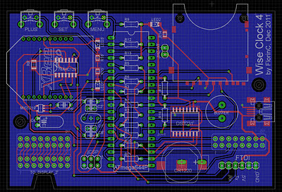
The board layout, shown below, can be downloaded from here.


This is really great, so it can display the latest news too!
ReplyDeleteIs there a kit available soon?
Kits are available, but the software to handle the XBee is not. As of now, Wise Clock 4 looks like (and runs the same software as) Wise Clock 3.
ReplyDeleteHi FlorinC
ReplyDeleteAre you also working on the enhanced code for wiseclock 3? (kitchen timer etc?) please let us know when such enhancement would be available.
Anjan
I am trying to, but I am very busy these days. I will publish every piece of code as soon as it works.
ReplyDeleteThanks FlorinC! Very much appreciate all your efforts!
ReplyDelete