Tuesday, May 27, 2014

Single-digit Nixie tube micro clock

This single-digit Nixie clock is built on a piece of prototype board, as a ProMini shield, similar to two previous miniature clocks, the single-digit numitron clock and the 7-segment bubble clock. The shield holds the Nixie board and the high-voltage power source (both from Taylor Electronics). It also has a couple of buttons to set up the time and 4 LEDs to indicate the digit's position.


Like the single-digit numitron clock, time is displayed by showing each of the 4 digits (as in HH:MM). But for a "clearer picture", I added the above-mentioned 4 different color LEDs.
One of its nice features is that it works on the rechargeable 3.7V LiPo battery.


The clock does not have an on-board RTC (lack of space), relying instead on the time-measuring capabilities of ATmega328 directly. So this clock will keep time for as long as the battery is kept charged (through the USB power cable).

The photo below shows my "collection" of (un-synchronized) micro clocks. (Missing is the numitron clock, which requires a stand; I am still waiting for a part to build that).


The right-most one follows the same ProMini shield idea, using an I2C OLED display and running the Pong sketch (courtesy of miker).

Thursday, May 8, 2014

Tiny single-digit numitron tube clock

There is no "dumb" display easier to connect to an Arduino (or any microcontroller, for that matter) than a numitron tube, even compared with the 7-segment LED display. This is because:
  • unlike LEDs, it does not need current-regulating resistors;
  • unlike LEDs, the segments are not polarized; just connect any end of a segment to Vcc and the other to ground and it lights up; basically, every segment is the filament of a light bulb, like those used in flashlights in the old days; like light bulbs, they even get warm after a while (hence their inefficiency);
  • voltage range is pretty wide, between 2V and 5V;


The most popular numitron tube is IV-9, which can be purchased these days on ebay for $5.
Size-wise, IV-9 fits perfectly on a Arduino ProMini board, and so it can be soldered directly into the bottom holes of that board. The clock I made displays the HHMM-formatted time as a sequence of 4 digits. Since there is no RTC on board, the processor keeps track of passing time. The rechargeable LiPo battery plays the role of the backup power, in case the USB cable is unplugged. The current consumption is about 20mA per segment, making the clock draw between 50mA and 160mA. With the on board 240mAh LiPo battery, the power would last for a maximum of 2 hours. The display can be turned off (left button) to save power, thus making it suitable as a wearable device (watch). In this case, the clock draws only about 10mA.
The right button is used for setting up the time.


The numitron clock doesn't get any smaller than this.


The cost of building this tiny numitron clock is about $12:
- Arduino ProMini, with ATmega328 (about $3 on ebay);
- IV-9 numitron tube ($5 on ebay)
- LiPo charger module ($2 on ebay)
- 240mAh LiPo battery ($2 on ebay)
- 2 tactile push buttons ($0.5 on ebay)

The only problem I had was with the ProMini bought on ebay. Sometimes they come with no bootloader burned on the microcontroller. Once anything is soldered on the board (e.g. headers), burning the bootloader through the ICSP becomes almost impossible (because of space constraints).
Therefore, before including it in a project, always test the bare ProMini by uploading a sketch.


Sunday, May 4, 2014

Prototype clock with HDSP-2534 smart display

I recently had the opportunity to acquire a few HDSP-2534 smart alphanumeric displays on the cheap. They seem to be vintage electronics (mines are stamped 9802, by HP), but they are still being made by Avago and sold by digikey (for about $40 a piece).

From the datasheet, the HDSP-253x looks like the LED dot-matrix equivalent of an HD44780-controlled LCD display:
  • data is sent on a 8-bit bus;
  • ability to decode 128 ASCII characters, which are permanently stored in ROM;
  • allows definition of 16 user-programmable symbols that are stored in the on-board RAM.

I wired the display to an ATmega328 (internal oscillator at 8MHz) through a 595 shift register, using the schematic in this post from nycresistor blog.


They use the HDSP-2111 display, which is very similar to the HDSP-2534 I have. They also provide demo source code for writing data to the display. Needless to say everything works as described. My contribution to the code is a function that sets the display brightness at one of the predefined 7 levels.


As shown in the photo above, all components fit on a 5cm x 7cm prototype board. The RTC is DS1307 with backup battery. The hours and the minutes can be set from the two buttons.

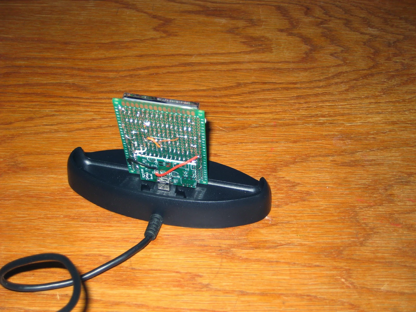
The easiest solution to "finish" the clock was to mount it on a phone dock charger I had around (which can be also found on ebay for $3 or so). Plugging the clock board into the dock's USB connector requires a "breakout" miniB (like this one sold by adafruit). I improvised one by cannibalizing a Geiger PCB, as shown in the photo below.


The "breakout" miniB connector is attached to the back of the clock board by soldering a few header pins in matching holes of the 2 boards. The assembly is mechanically solid.


The current draw at the lowest brightness (which is still very visible, as shown in the photo above) is between 20 and 40mA. At the highest brightness, the clock draws about 200mA.


Future improvements may include a Bluetooth module to display messages sent from a smart phone. And of course, designing a proper PCB :)

Update (Jul 20, 2014): A kit for this clock is now available.


Tuesday, April 8, 2014

Micro clock with 7-segment bubble display

Updated Aug 30, 2014: A kit for this clock shield is now offered here.

I am not particularly attracted by 7-segment LED displays, but I liked the HP bubble display that Sparkfun started selling recently. Like with the Nixie tubes, there aren't many things one can build with them, and my obvious choice was a clock. Being one of the smallest 7-segment LED displays out there, the clock had to be miniature as well. It took some thinking and planning to come to this final "design":


This micro clock uses the Pro Mini sandwiched between the LiPo battery undershield and the display shield (that also includes the RTC), both DIY on protoboard.


The LiPo undershield uses a cheap (less than $1 on ebay) USB charger board, which also provides the USB connector for power, since Pro Mini does not have one. The small 180mAh LiPo battery sits on top of the charger, but still allowing the 2 LEDs ("charging" and "charged") to be visible. There is also a switch for turning the battery power on or off. The clock is normally powered from a USB power adapter, but it can also work on battery for about 9 hours (the measured average current draw is around 20mA) when the USB cable is not plugged in. In this latter case, it can be turned on from the power switch to show the time only when needed.

The display shield is oversized to make the clock sit at an angle. This solution also provided enough room to include the RTC chip and the backup battery. Actually, and this will probably be the topic of a future post on DIY miniaturization, I did not have a choice for creating a separate RTC shield. The machined headers I used, not the stacking kind (which would have been disproportionately big), only allowed a top and a bottom shield around the Pro Mini board.


As one can imagine, the sketch is trivial (after reading the excellent Sparkfun tutorial :) and based on the SevenSeg arduino library.
But there is always a little glitch somewhere. In this case, I misinterpreted the datasheet. Normally, digit 1 is the left (most significant) one. My wiring assumed digit 1 is the rightmost (least significant) digit.
I fixed it in software: redefined digit1...digit4, then rotated segments (segA to SegF) 180 degrees.


#include "SevSeg.h"
#include < Wire.h >
#include "DS1307.h"

SevSeg myDisplay;
unsigned long timer;

void setup()
{
   int displayType = COMMON_CATHODE;

   // arduino pins connected to cathodes;
   int digit1 = 15; //Pin 1
   int digit2 = 13; //Pin 10
   int digit3 =  3; //Pin 4
   int digit4 = 14; //Pin 6

   // arduino pins connected to the segments (anodes);
   int segC =  6; //Pin 3
   int segE =  4; //Pin 2
   int segG =  5; //Pin 7
   int segB = 12; //Pin 11
   int segD =  8; //Pin 8
   int segF = 11; //Pin 9
   int segA =  7; //Pin 12

   // not connected yet;
   int segDP= 10; //Pin 5

   int numberOfDigits = 4; // this display has 4 digits;

   // initialize the 7-segment display object;
   myDisplay.Begin(displayType, numberOfDigits, digit1, digit2, digit3, digit4, segA, segB, segC, segD, segE, segF, segG, segDP);

   myDisplay.SetBrightness(100); // 100% brightness

   timer = millis();
}

void loop()
{
  int rtc[7];
  RTC_DS1307.get(rtc, true);
  int minute = rtc[DS1307_MIN];
  int hour   = rtc[DS1307_HR];
  char timeString[10];
  sprintf(timeString, "%02d%02d", hour, minute);
  myDisplay.DisplayString(timeString, 0);

  if (millis() - timer >= 1000)
    timer = millis();
}

The next version of the bubble clock should use two displays (8 digits), showing the seconds as well.


Saturday, April 5, 2014

The simplest Arduino LCD Clock

I wrote up this post in response to the many inquiries I get about Arduino school projects.

Here I describe how to build the most basic (and probably the lowest cost as well) Arduino clock, using a real time clock (RTC) chip and a 1602 LCD display (2 lines of 16 characters). Unlike most of the LCD clocks out there (the only notable exception being Kevin Rye's LCD clock), this one is also encased and ready to be used in real life. Actually, the build starts with the enclosure (the very affordable adafruit LCD stand), which drives the requirements for the rest of the components.

Note: This LCD clock does not have any buttons. The time and date are set with the serial monitor (or Hyperterminal or any other serial console), by sending specific commands. I was thinking of adding the Bluetooth module, but then the process would be the same (or maybe even more complex, if you consider the pairing step), and it would only replace the PC with an Android phone or tablet.
Using serial monitor makes sense because the Pro Micro already has on-board USB interface, that is, one doesn't need the extra FTDI cable to communicate with the PC (also requiring attention to the connector's orientation when plugging it in).


List of materials
  • LCD stand - from adafruit;
  • 16x2 LCD - from various sources: adafruit, sparkfun, ebay;
  • Pro Micro (sparkfun's original or clones from ebay) - board compatible with Arduino Leonardo, chosen because it is the only one fitting the LCD stand, both in size and the position of the USB connector;
  • prototyping PCB - I used this, but many others can be found on ebay;
  • 10k trimpot (for adjusting the contrast on LCD);
  • DS1307 real time clock IC + 32kHz crystal - from ebay;
  • CR1220 coin battery + battery holder - from ebay;
  • two 10k resistors (pull ups for I2C lines);
  • a bunch of wires;
  • micro USB cable - from ebay;
  • 16-pin male header and 16-pin female header - from ebay;
  • USB power adapter.

Depending on the component sourcing, the cost for the whole project can vary between $20 (ebay) and $45 (adafruit, sparkfun).


Step 1
Solder the 16-pin male header onto the LCD display.

Step 2
Assemble the LCD stand including the LCD as well, selectively following the manufacturer's instructions.


Step 3
Cut a piece of prototyping PCB to match the size of the LCD. This will be used as a "backpack" (plugged into the LCD) holding the Pro Micro board, the RTC and the battery.

Step 4
Solder the female header onto the backpack in the appropriate position (so that it can be plugged into the LCD).

Step 5
Solder the small Pro Micro board on the PCB so that the micro USB connector matches the side opening of the stand, also making sure that the micro USB cable can be plugged in through that opening.
Then wire the Pro Micro to the header of the LCD display, as follows:
  • pin A1 of Pro Micro to pin 4 (RS) of LCD
  • pin A0 of Pro Micro to pin 6 (EN) of LCD
  • pin 16 of Pro Micro to pin 11 (D4) of LCD
  • pin 10 of Pro Micro to pin 12 (D5) of LCD
  • pin 15 of Pro Micro to pin 13 (D6) of LCD
  • pin 14 of Pro Micro to pin 14 (D7) of LCD
  • LCD's pins 1, 5 and 16 are wired to ground
  • LCD's pin 2 is connected to Vcc (5V)
  • LCD's pin 3 is connected to the 10k trimpot slider (middle pin), used for adjusting the contrast
  • LCD's pin 15 (backlight LED) is connected to Pro Micro's pin 9.
A good tutorial on connecting a 16x2 LCD to Arduino can be found here.

Step 6
Solder the RTC, battery holder and crystal, then connect the I2C lines (SDA and SCL) to the Pro Micro, according the the schematic below.


DS1307 talks to any microcontroller on I2C, through 2 wires named SDA and SCL. Unlike Arduino 2009 or UNO (with ATmega328) where SDA and SCL are on pins A4 and A5 respectively, Leonardo and Pro Micro (with ATmega32u4) use pins D2 and D3 as SDA and SCL.

We also need to pullup the I2C lines (SDA and SCL), by connecting D2 and D3 to Vcc through the 10k resistors. The final result is shown in the photo below.


I used the SMD version of DS1307, soldered on the PCB's plated side (see photo below). Also note the trimpot, soldered on the same side for accessibility.


Step 7
Familiarize yourself with the Pro Micro (or the equivalent Arduino Leonardo). Read about how to install the board's driver, if this is the first time you use it.

Step 8
Download the sample sketch, compile (in Arduino IDE 1.04 or later, after you made sure that "Arduino Leonardo" is selected as the current board), then upload.

Step 9
Open the serial monitor and set the current time by sending the command TIME=hh:mm:ss, where hh is the actual hour and mm is the actual minute (e.g. TIME=08:25:00 or TIME=15:42:38).
As well, set the date by sending the command DATE=yy/mm/dd, e.g. DATE=14/04/03.

Step 10
Disconnect the USB cable from the computer and power the clock from the USB power adapter.
The time and date are displayed as shown in the photo below.


Troubleshooting
  • If the LCD does not show anything:
    • adjust the trimpot for contrast;
    • check the wiring, by making sure the connections are right, according to the list in step 5;
    • check that there are no shorts between pins.
  • If the date and/or time show 0:
    • check that the DS1307 is connected correctly to pins D2 and D3 and to the rest of components, according to the schematic in step 6;
    • check that the backup battery provides 3V and is inserted properly.