Saturday, October 31, 2009

Testing Duino644 - "Wise Clock 2" main sketch

Updated Feb 18/2010

The latest version of the "Wise Clock 2" code library can be downloaded here. This was tested and confirmed working in Arduino 17 (on Windows) with the sanguino libraries.

The library includes functions/classes from the following:
  • DS1307;
  • a modified version of the SDuFAT library;
  • font3.h, the definition of the character set;
  • Tone library;
  • HT1632 library (for the Sure Electronics LED display), written by westfw. (HT1632 functions are included directly in Wise4Sure.pde sketch.)

Note: If you already have DS1307.zip installed, you may get an error saying that DS1307 is defined in multiple places (it is already included in WiseClock2.zip). If that is the case, delete the DS1307 folder from hardware/libraries.

Now bring on your 16x24 LED display from Sure Electronics to see Wise Clock 2 in action.
Plug the display into the Duino644 board (or vice versa :). Make sure that the display has the CS1 in the "ON" position and the other three switches are set to "OFF".
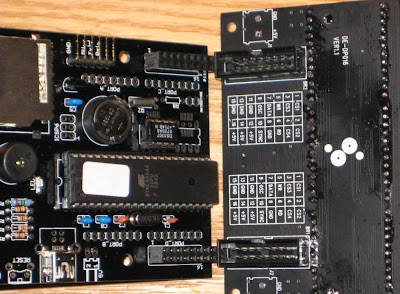

Note: The LED display board has a pair of 2-pin screw terminals on the back (face opposite to LED matrices). They may impede the Dunio644 to plug into the display board. Even if that is not the case (it did not happen to me so far), it is a good idea to extract those screw terminals, which can be useful somewhere else. The picture above shows the LED display board with the screw terminals removed.


Next, copy the two text files, time.txt and quotes.txt onto the SD card, after you made sure the card is formatted as FAT16. For information on how to check the formatting, follow this article on adafruit website.

Open the file time.txt in a text editor and modify the line containing the time. This will be the time used for setting the RTC, and it happens when the clock is powered with the time.txt file on the SD card. (After the time was set, the file is "deleted". See more information here.)

Now, after uploading the sketch to Duino644 board, the text from the file quotes.txt should be scrolling on the top half of the display, and the time should be displayed on the bottom half, as shown in this video.

Congratulations! It is now the time (pun intended :) to design a nice enclosure and to show it off to friends and family.


Related posts:

Thursday, October 29, 2009

Testing Duino644 - RTC and EEPROM

With the Duino644 kit assembled, we can now start testing it.
First, plug the USB cable in the USB miniB onboard connector and make sure the blue LED is lighting.
Alternatively, plug in the FTDI connector (or "FTDI basic breakout"), making sure that the USB (power-only) cable is unplugged. Unlike Wiseduino board, Duino644 is powered by the 5V FTDI pin. Blue LED should be on.


Before uploading any sketch to Duino644, we need to install the Sanguino libraries. (Remember that Duino644 is compatible with Sanguino.) At the end of the integration we will see Sanguino listed in the Tools/Board menu of the Arduino IDE. This is the board that must be selected when working with Duino644.

Before proceeding further, we need to modify boards.txt file, specifically the "Sanguino" section, to look like this:

sanguino.name=Sanguino
sanguino.upload.protocol=stk500
sanguino.upload.maximum_size=63488
sanguino.upload.speed=38400
sanguino.bootloader.low_fuses=0xFF
sanguino.bootloader.high_fuses=0xDC
sanguino.bootloader.extended_fuses=0xFD
sanguino.bootloader.path=atmega644
#sanguino.bootloader.path=atmega644p
sanguino.bootloader.file=ATmegaBOOT_644.hex
#sanguino.bootloader.file=ATmegaBOOT_644P.hex
sanguino.bootloader.unlock_bits=0x3F
sanguino.bootloader.lock_bits=0x0F
sanguino.build.mcu=atmega644
#sanguino.build.mcu=atmega644p
sanguino.build.f_cpu=16000000L
sanguino.build.core=sanguino
sanguino.verbose=false

This is because Duino644 comes with ATmega644 instead of Sanguino's ATmega644P. The difference between the two processors is a second UART in ATmega644P.
(Note: Future revisions may ship with ATmega644P, although the extra functionality is not required nor used in Wise Clock 2.)

Using the FTDI cable, upload the first sketch, the one that sets the real time clock.
(Note: This is just for testing the RTC, since the clock itself can be set using the method described here).

If you feel adventurous you can start directly with the main sketch. It should work, unless you skipped a step or two (forgot to insert the DS1307 chip in the socket, for example) .

Download this file and unzip it in the hardware/libraries folder of your Arduino IDE.
It contains rtc.pde sketch and DS1307 class (header and cpp files).

To set the clock, un-comment the portion of the code in setup(), upload the sketch and run it once. To avoid setting up the same time at every reset and power-up, modify the sketch by commenting out the setup() portion, then upload it again. Now, the board will just send back the time from RTC on serial port.

Testing the EEPROM is done similarly with Wise Clock and detailed here.
(Note: The Wise Clock 2 functionality does not use the EEPROM so far. In the "glass dome" Wise Clock, the quotations were stored in EEPROM, there was no SD card.)

If everything works fine so far, let's take the big jump and load the sketch for Wise Clock 2, which reads the SD card and displays the content of quotes.txt file onto the LED display.

So, next step is the last, and most important, one: uploading the main sketch.

Friday, October 23, 2009

Other "uzes" for Duino644

As mentioned in an earlier post, Duino644 can form the base for an implementation of the Uzebox project. A "uzebox shield" would be plugged in the Duino644 board, much as shields are used with Arduinos. The picture below shows my current effort in trying to get the "uzebox" working. Soldering is done, testing/debugging is next.


A few changes (from the Wise Clock setup) are required:
  • ATmega644 has a different firmware burnt in (not the Arduino/Sanguino bootloader);
  • the microcontroller, nominal frequency of 20MHz, is overclocked at 28.63636 MHz.
Many components on the main board are not necessary (RTC, battery, EEPROM etc). Instead of the LED display (2x8 female header) connectors, the four extension (8 pin female header) connectors are used.

I will post the results of this experiment later. I also plan to design a "uzebox shield" PCB.

On the same note (other uses), it was pointed out by fellow Arduino enthusiast BroHogan, of X10 fame, that the Duino644 is also compatible with his Nex10 board (I am grateful for the link on his page), so it can be used as the base for my next X10 project (following his instructions, obviously).

I will keep you posted on the Nex10 project as well, hopefully I will find the time to do it.

Saturday, October 17, 2009

Duino644 software updates

I was close to giving up on SDuFAT library in favour of FAT16, but my one last attempt worked. I was trying to implement a feature suggested by fellow Arduino blogger BroHogan, to set up the clock using a file on the SD card. Since real time clock is set up quite rarely, this idea makes perfect sense.
Here is how it works:
  • the user creates/copies the file "time.txt", which contains the time, formatted as HH:MM:SS, onto the SD card;
  • after reset, if "time.txt" is found, the clock is set with the given (in the file) time;
  • "time.txt" file is deleted, so the next reset won't find the file anymore;
It is always easier said than done.
Firstly, SDuFAT requires the file to have some characteristics, the most important being to contain a pseudo-EOF (0x03) character.
Secondly, the deletion of the file is not physical, the file does not disappear from the SD card, but it is rather modified so that its first character is the pseudo-EOF (0x03). The "deleted" file can be opened and its content read. The code decides that the file is "deleted" by checking the first character. How smart is that?

setRtcFromSDCard() shown below is the function that gets called in setup().

void setRtcFromSDcard()
{
numSectors = (int) SD.getSectors("time.txt");
if (numSectors == 0)
{
// try again;
delay(500);
numSectors = SD.getSectors("time.txt");
}

if (numSectors == 0)
{
#ifdef _DEBUG_
Serial.println("File time.txt not found.");
#endif

return;
}

// open file time.txt and read its content;
sectorContent = SD.readBytes("time.txt", 0);

// search for the time in the sector buffer;
boolean isTimeFound = false;
for (int i = 0; i<512; i++)
{
if (sectorContent[i] == 0x03)  // EOF
break;

for (int j=0; j<8; j++)
{
timeBuffer[j] = sectorContent[i+j];
}
if (timeBuffer[2] == ':' && timeBuffer[5] == ':')
{
// found the time;
isTimeFound = true;
break;
}
}

if (!isTimeFound)
{
#ifdef _DEBUG_
Serial.println("Could not find time (HH:MM:SS) in file time.txt");
#endif
return;
}

#ifdef _DEBUG_
Serial.print("Time from file is: ");
Serial.println(timeBuffer);
#endif

int hh = 10*(timeBuffer[0]-48) + (timeBuffer[1]-48);
int mm = 10*(timeBuffer[3]-48) + (timeBuffer[4]-48);
int ss = 10*(timeBuffer[6]-48) + (timeBuffer[7]-48);

#ifdef _DEBUG_
Serial.print("RTC time to be set to: ");
Serial.print(hh);
Serial.print(":");
Serial.print(mm);
Serial.print(":");
Serial.println(ss);
#endif

if (hh < 24 && mm < 60 && ss < 60)
{
setTime(hh, mm, ss);
SD.del("time.txt");
}
}


The other software change I made was also the contribution of BroHogan, who wrote (see reply #147) a few functions that perform "fast writes" to the LED display from Sure Electronics. Basically, the calls to digitalWrite() in ht1632_writebits() function have been replaced with calls to fWriteA(). This allows control over the speed of scrolling, ranging from fast to slow, rather than from slow to slower.


Monday, October 12, 2009

New Duino644 kit (revision 1.1)

Thanks for ordering Duino644 kits.
At the moment, all of the "original", revision 1.0 (first batch of) PCBs are gone. In the meantime, I designed an improved version, by adding a few more components, to bring it closer to its intended functionality as the backbone of the Wise Clock:
  • 3 right angle push buttons (for setting up time, snooze, dimming etc);
  • piezo buzzer, for the alarm;
  • bright blue LED, as a background (and power indicator) light;
  • a bit bigger PCB.
This is the schematic for revision 1.1 of Duino644 (download Eagle file here):

and this is the board (download Eagle file here):

To my estimation, I should receive the new PCBs by Oct 20.
Once the new boards are in, I will have to re-price the Duino644 kit to cover the cost of the extra components, essentially increasing it by US$4, to a total of US$58 (free regular shipping to North America) and US$62 (free shipping outside North America) respectively.

The orders placed until then, at the old prices, will be filled with the new design. Consider this as a "promotion" campaign and take advantage of the "reduced" price.

See also: