- all components except the RTC chip DS3231 (which comes soldered to the board) are through-hole;
- the spot and orientation of each component are printed on the board very clearly;
- sockets are provided for each integrated circuit;
- placing and soldering the components takes a few hours;
- it is very important to pay attention to the correct orientation of the polarized components (LEDs, electrolytic capacitors, transistors, ICs), since any mistake takes time and effort to repair;
- double check every time before soldering any component, even resistors.
The C3Jr kit you received includes (as shown in the photo):
- large (18cm x 23cm) PCB;
- ATmega328 with 28-pin socket;
- 16MHz crystal + two 22pF capacitors;
- 74LS154 and 24-pin socket;
- STP08DP05 and socket;
- DS3231, pre-soldered to the board;
- CR2032 (3V) coin battery and battery holder;
- 130 diffused white (or blue, on request) 5mm LEDs;
- 17 PNP transistors 2N5401;
- 4 decoupling capacitors 100nF;
- 100uF electrolytic capacitor;
- 17 resistors 100 ohms;
- 6 resistors 10K;
- 2 resistors 4K7;
- 2 resistors 1K;
- 2 resistors 680 ohms;
- USB type B (power) connector;
- speaker/buzzer;
- 6-pin right-angle male header used as FTDI connector;
- 4 right-angle push buttons;
- 5k potentiometer;
- set of laser-cut, black plastic, baffles;
- laser-cut acrylic faceplate with your favorite choice of font;
- laser-cut plastic backplate;
- set of standoffs, screws, nuts, washers.

The step-by-step assembling instructions are presented below.
1. Place and solder the 100 ohm (brown-black-brown) resistors, 17 of them.

2. Place and solder the 6 resistors of 10K (brown-black-orange).
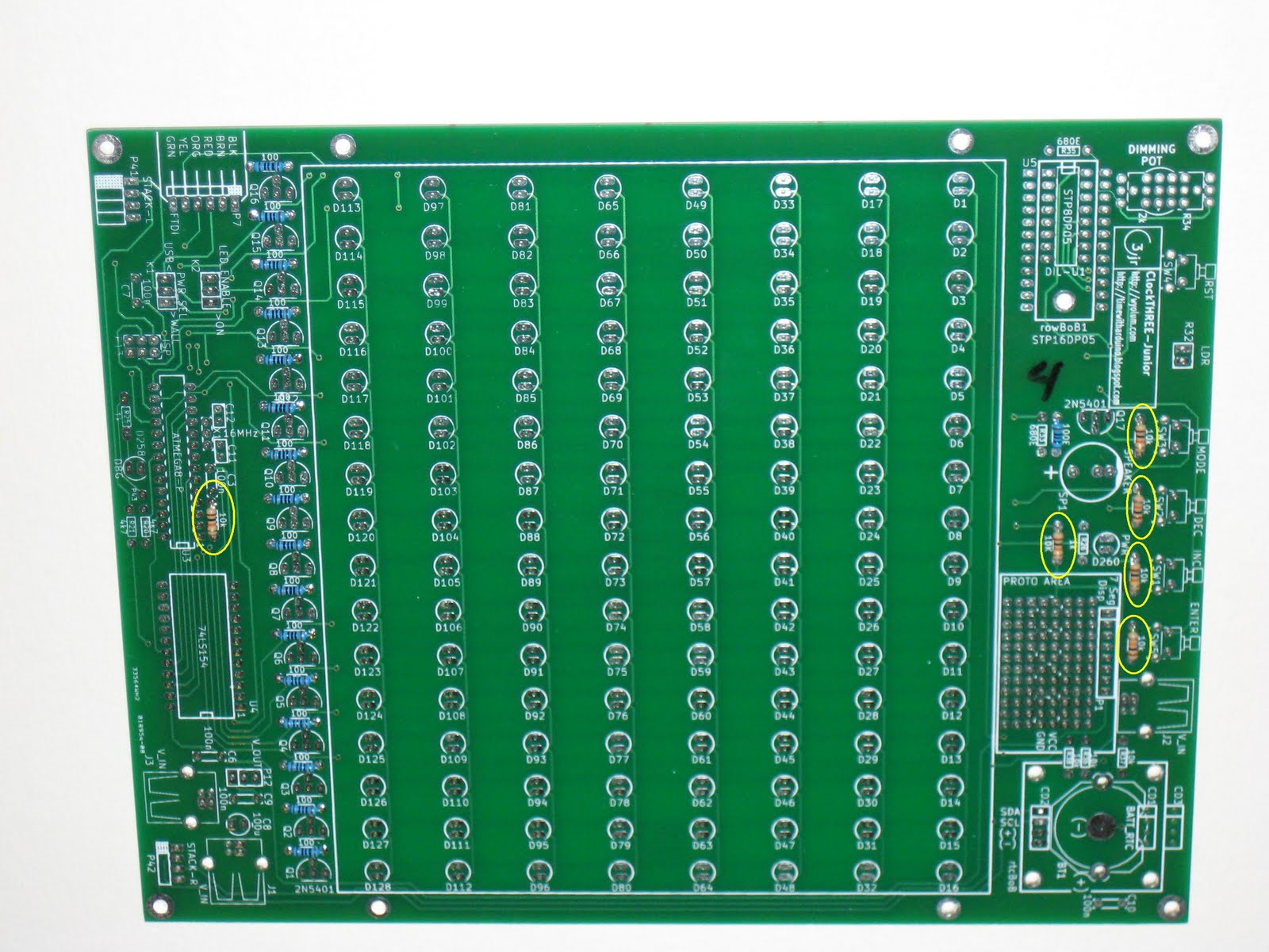
3. Place and solder the 2 resistors of 4K7 (yellow-purple-red), then the 2 resistors of 1K (brown-black-red), then the last 2 resistors, of 680 ohm (blue-grey-brown), as shown in the photo below.

4. Insert and solder the sockets for integrated circuits marked U3, U4 and U5. There are 3 sockets and they need to be placed with the notch matching the silkscreen markings. The photo below shows (in the upper-right corner) 2 rows of 12 machined female pins (also used as IC socket) where normally is the place for the 16-pin 0.3" socket.
If it happens to solder any of these sockets with the wrong orientation, don't try to fix anything; just make sure that the ICs are inserted with the correct orientation, matching that on the PCB's silkscreen.

5. Place and solder the decoupling capacitors (100nF), then the electrolytic capacitor (100uF), as shown in the next photo. The 100nF capacitors don't have polarity, so their orientation is not important. But the 100uF electrolytic capacitor (black small cylinder) must be positioned with the negative terminal (marked with a minus) closer to the right edge of the board.

6. Place and solder the USB type B connector (used here as power jack), in one of the 3 available spots, depending on how the clock will be displayed: J3 if on the wall or J1 if on the desk. (In the photo below, the USB connector is mounted for a desk configuration.) Then solder the 6-pin male right-angle header (used as FTDI connector) and the two 3-pin male headers. Next, solder the buzzer, the resonator (or crystal + 2 capacitors), the four right angle push buttons, the coin battery holder and finally the dimming pot. The board should look now like in the photo below.

Note that the RESET button and the debug LED are optional (and not populated on the board in the photo).
7. Solder the 17 PNP transistors, their orientation according to the silkscreen.

8. Solder the LEDs. Pay maximum attention to their orientation. The short pin is the cathode (negative terminal). The cathode is also indicated by a straighten arc at the bottom of LED's plastic capsule, see the drawing below.

When placing the LEDs, their cathode (short terminal) always goes toward the label on the silkscreen.
The board with the LEDs soldered looks as in the next photo.

There are 2 optional LEDs in addition to the 128 LEDs in the matrix: one (D260) is the power indicator and may be annoying since it is ON all the time, the other (D258) is used for debug purposes.
9. Insert the ICs into their respective sockets. Before doing this, bend all the pins on each side at once, by pushing them against the table, so both rows of pins become parallel.
Make sure the notch of each IC, indicating where the pin counting starts, matches the notch in the silkscreen (and also on the socket, if you place those correctly in Step 4).
The ATmega328 microcontroller comes programmed with the latest release of the C3Jr software. New sketches can be uploaded, with the Arduino IDE, through the FTDI cable/breakout (plugged into the 6-pin FTDI connector).
10. Assemble the enclosure, starting with the backplate/bottom plate. Insert the 4 long screws into the 4 holes closer the center of the backplate. Secure each with a small nut as shown in the photo below.

Slide the completed PCB on the protruding screws, with the buttons near the two keyholes at the top of the backplate. Then place each of the 4 small baffle locators on every screw and secure with the 4 small nuts, as shown in the next photo.

Interlock the baffle grid into place with the angled edge against the PCB. This provides a little extra space for the components. You can start with the top and bottom vertical pieces and slide all the horizontal pieces into place. Place the whole assembly on a flat surface (cardboard, book etc) and flip over, then transfer it over LED matrix region of the PCB. You can now install the remaining vertical pieces. Next, insert the 4 screws into each corner of the backplate and secure with the 20mm standoffs.

Note that the protection-paper on the baffles is still there. I did not bother to peel it off, but it doesn't seem to affect the functionality. After all, the purpose of the baffles is just to separate the LEDs in the matrix.
Install the faceplate on top of the baffles and secure with the 4 provided socket screws.

11. Power up the clock with the USB type-B cable, similar to those used for USB printers. (You can also use the FTDI cable to power it up, but ensure that the PWR SEL jumper is in the correct position, on the left 2 pins.)
Since the microcontroller is loaded with the latest C3Jr software, the clock will work right away (you just need to set the time.)


Very cool collaboration!
ReplyDeleteDuly added to the spreadsheet (also the DWex which I'd missed):
http://tinyurl.com/allarduinos
Also, C3jr is listed as "open source hardware" but where are schematics or board files? I'm trying to figure out what the "STP8DP05" is, looks like an NXP chip but searches turn up nothing...
salsa, thanks.
ReplyDeleteI will add the schematic and board files.