This is a long-overdue piece of documentation, which I started many months ago and never had a chance to finish. It may not be totally complete even now, but at least it gives some direction towards the integration of the XBee radio and Wiseduino.

The XBee adapter should be plugged in as shown in the following photo:

Beside the wireless communication, the XBee adapter provides a few more services:
- remote sketch upload;
- 3V3 for the main board, usable by other shields (about 50 mA worth);
In order to use it with Wiseduino as in the setup shown above, the XBee adapter requires a few little modifications.
1. The first is a trace cut, as pictured below:

Basically, the two extreme holes for the header are connected together, and to 3V3. We are going to use one of these redundant connections for our purposes, and that is to access XBee's pin D3 from the Wiseduino board (as explained in adafruit's XBee tutorial).
2. Secondly, the straight header (provided in adafruit's kit) must be soldered perpendicular to the board.
3. Thirdly, a wire needs to be soldered between D3 and the extreme left pin of the header (the one that was isolated at step 1 by cutting the trace).

Before inserting the XBee radio module, the adapter should look like in the photo below.

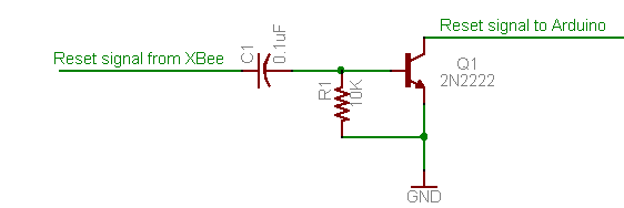
After the hacks are done, for the remote sketch upload, just follow adafruit's great tutorial.
Notice that the small circuit with the transistor in the mentioned tutorial is already implemented on the Wiseduino board.
Related posts:


No comments:
Post a Comment