Thursday, February 18, 2010

Memory mapping in 16x24 LED displays from Sure Electronics

When Sure Electronics released their green version of the 16x24 LED display, I was surprised to notice that this display was not compatible with the red one. One could not just unplug the red display and replace it with the green one and expect it to work. I found out about this the hard way. After a bit of confusion (I thought that my green display was defective), it was pointed out to me that the datasheets for the two displays are different. It took a little effort to accommodate the green display in the Wise Clock 2 software. Essentially, I had to adapt the function ht1632_plot to work with the new display.

I show below some diagrams representing the memory mapping for the two displays.
The datasheets (red here, green here) do not explain this mapping very clearly. I thought my drawings may bring some better understanding to others as well.


Friday, February 12, 2010

Assembling the "Dual Bi-color LED matrix shield" kit

This kit contains the following parts:
  • PCB (compatible with Arduino shields);
  • two 8x8 bi-color bright LED matrices (side is 47mm or 1 7/8" in length, 5mm LEDs);
  • 4 x 74HC595 shift registers;
  • ULN2803 transistor array;
  • 4 x 16-pin IC socket;
  • 32 current-limiting resistors;
  • 4 x 100nF decoupling capacitors (color may vary);
  • 4 x 12-pin machined female headers;
  • 40-pin male header;
  • rotary encoder with push button and knob.

To assemble the kit, follow the step-by-step process below.
  1. insert the four 16-pin IC sockets, making sure that their notches match those in the silkscreen; their orientation is important (errors are not fatal though), since it will indicate the orientation of the ICs which will be later plugged into them; solder the sockets, making sure that they are close to (touching) the board;


  2. cut the 40-pin male header in 4 pieces, two 8-pin and two 6-pin, then solder them in their corresponding places; these are the pins which will plug into Arduino's (female) extension headers; as always with the shields, it is advisable to have them plugged into the Arduino extension connectors while soldering them to the shield;


  3. solder the four 12-pin female headers; these are the connectors for the LED matrices;


  4. solder each resistor after placing it vertically (bend one terminal 180 degrees);


  5. solder the decoupling capacitors;


  6. place the ULN2803 chip, paying attention to its orientation (notch on chip must match notch on silkscreen) and solder it;
  7. carefully insert the integrated circuits into their respective sockets, matching the notches (socket-chip); to make sure they can be inserted, bend the pins on both sides just a tad (as shown here, courtesy of adafruit), so they become parallel;


  8. insert the LED matrices, paying attention to their orientation: pin 1 of the matrix must match pin 1 on the board (the pin numbers are hand-written by me on the back).


    The assembled shield should look like the one below.


    Related posts:

Thursday, February 11, 2010

Wiseduino and XBee

This is a long-overdue piece of documentation, which I started many months ago and never had a chance to finish. It may not be totally complete even now, but at least it gives some direction towards the integration of the XBee radio and Wiseduino.

One of the features of Wiseduino is the ability to plug in an XBee adapter from adafruit, in the designated 10-pin female header (provided in the Wiseduino kit). The intention is for this header to be soldered on the back of the board, as shown in this photo:


The XBee adapter should be plugged in as shown in the following photo:


Beside the wireless communication, the XBee adapter provides a few more services:
  • remote sketch upload;
  • 3V3 for the main board, usable by other shields (about 50 mA worth);

In order to use it with Wiseduino as in the setup shown above, the XBee adapter requires a few little modifications.

1. The first is a trace cut, as pictured below:


Basically, the two extreme holes for the header are connected together, and to 3V3. We are going to use one of these redundant connections for our purposes, and that is to access XBee's pin D3 from the Wiseduino board (as explained in adafruit's XBee tutorial).

2. Secondly, the straight header (provided in adafruit's kit) must be soldered perpendicular to the board.

3. Thirdly, a wire needs to be soldered between D3 and the extreme left pin of the header (the one that was isolated at step 1 by cutting the trace).


Before inserting the XBee radio module, the adapter should look like in the photo below.


After the hacks are done, for the remote sketch upload, just follow adafruit's great tutorial.
Notice that the small circuit with the transistor in the mentioned tutorial is already implemented on the Wiseduino board.

Related posts:

Tuesday, February 9, 2010

"Finished" Wise Clock 2 with Duino644

By "finished" I am only referring to the enclosure, not to the evolving (hopefully) software. Once released to the open source community, the software should be, in theory, never "finished", like a piece of art :)

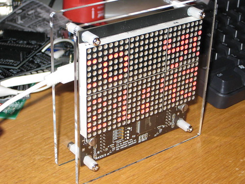
Here is a photo of a simple (and cost-effective), yet elegant, enclosure, consisting in two laser-cut sheets of 1/8" plexiglass separated by plastic spacers.

Sunday, February 7, 2010

Introducing the "Dual bi-color LED matrix shield"...

Updated Sep 29, 2011
Check out the newest LED matrix shield here


Updated Dec 18, 2010
A newer and better revision of the "Dual LED matrix shield" is available. Check it out here.
As of today, instead of the rotary encoder, the kit includes an infrared receiver, a tilt switch and two right-angle push buttons (see photos here).


... or, in other words, an Arduino shield that has two side-by-side, red-and-green 8x8 LED matrices. As probably everybody in the Arduino community knows by now, the most straightforward way to drive all these LEDs is through shift registers, specifically 74HC595. Which is exactly the way this shield is built: it has 4 of the 595 chip, each driving 8 columns of the same color. The 8 rows are connected to 8 output pins of Arduino (3, 7-13) through the ULN2803 transistor array.

The schematic is shown below (download Eagle file here).


This is the layout of the board (download Eagle file here).


The two LED matrices cover the components on the board and they get plugged into machined female headers for sturdy and reliable contact.

The LED matrix is UVP-2788 (datasheet here) and its internal circuit diagram looks like this:


This shield is used as part of the IllyClock. Originally it was designed to accommodate a push button and an infrared receiver, but these two components were dropped for an external (not on-board, but connected through wires) rotary encoder with push button.

You can buy the dual matrix shield here, as a kit containing the following parts (as seen in the photo below):

  • PCB;
  • two 8x8 bi-color bright LED matrices (side is 47mm or 1 7/8" in length, 5mm LEDs);
  • 4 x 74HC595 shift registers;
  • ULN2803;
  • 4 x 16-pin socket;
  • 32 resistors;
  • 4 decoupling capacitors (100nF);
  • 4 x 12-pin machined female headers;
  • 40-pin male header;
  • rotary encoder with push button and knob (not pictured).

(US$35, free regular shipping to North America)

(US$40, free regular shipping outside North America)


Creative Commons License
This work by FlorinC is licensed under a Creative Commons Attribution-Share Alike 3.0 Unported License.


Related postings:

Friday, February 5, 2010

Introducing IllyClock - alarm clock in a coffee can

Updated Aug 3/2011
Check out the "minimalist" version here.


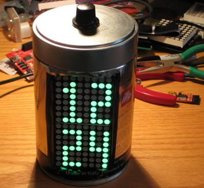
Borrowing from Ladyada's idea of encasing the MintyBoost in an Altoids tin box, I thought that a coffee can, Illy in particular, would make a good enclosure for an alarm clock.

The electronics is based on Wiseduino (Arduino clone with DS1307 real time clock on board), with a LED matrix shield sitting on top. The shield is built with 74HC595 shift registers that drive two bi-color (red, green, and orange by subtraction) 8x8 LED matrices.

The clock uses a rotary encoder with button as the only user input.
The functionality is simple and intuitive:
  • time is shown as hour and minutes;
  • clicking the button will show, using the symbol of a bell, the state of the alarm (enabled or disabled);
  • double clicking the button will show the alarm time and allow the user to set the alarm hour and alarm minutes (toggle between the two by clicking the button); increment the numbers by rotating the knob;
  • holding down the button will allow the user to set the time;
And here is an original feature: three hours before the alarm will sound, the time is shown in orange; one hour before the alarm will sound, the time is shown in red. So just by squinting at the clock, one can realize how much longer one can sleep.

Here it is in action:


A few details on the dual matrix shield can be found below.
(I will dedicate another post to this shield though.)


The shield was originally designed (as it is shown in the schematic above) to be equipped with an infrared receiver and a push button. "Hacking" it to take a rotary encoder instead is trivial.

The diagram below shows how the user can change the clock's state by either rotating the encoder or pushing the button.


Related:

Wednesday, February 3, 2010

Wise Clock 2 software release for February 2010

Updated Apr 1/2010
Here are a few things to consider when using the "Wise Clock 2" library:
  • make sure your boards.txt file describes the version of ATmega644 you have (644 or 644P); if you use the wrong description, you will get a "wrong signature" error when uploading the sketch;
  • in Arduino IDE 18, you may get a compilation error related to "main.o"; if that happens, copy the main.cpp file from hardware/... /arduino to hardware/.../sanguino;
  • line 48 in Wise4Sure.pde sketch (#define _GREEN_DISPLAY_) needs to be enabled/disabled according to the display you want to use; if you use a red display, then comment that line out;
  • there seems to be multiple versions of the Tone library; you may even have one already installed; in case you get an error related to Tone library, leave only the version coming with the Wise Clock 2 library (which is tested and confirmed working).

I uploaded a new release of the Wise Clock 2 software, which can be found here.

It includes support for the new, green, LED display from Sure Electronics, which has the display memory organized differently than the red one (I could not find a reason they would do that; just for the sake of change?).

It also includes a bug fix: parameters (scrolling speed, brightness etc) retrieved from the RAM of a fresh RTC (that is, they were never saved there), came back with bogus values (of course, how obvious was that?). The latest release detects this case and saves the default parameters before retrieving them.

I will soon post a video of the green display in action.